Design Guide | VLT® AutomationDrive FC 360
Table 28: P1 and P2 Endpoints (continued)
Input Analog 53
voltage mode
Analog 53
current mode
Analog 54
voltage mode
Analog 54
current mode
Pulse input 29 Pulse input 33
Maximum refer-
ence value
Parameter 6-15
Terminal 53
High Ref./Feedb.
Value
Parameter 6-15
Terminal 53
High Ref./Feedb.
Value
Parameter 6-25
Terminal 54
High Ref./Feedb.
Value
Parameter 6-25
Terminal 54
High Ref./Feedb.
Value
Parameter 5-53
Term. 29 High
Ref./Feedb.
Value
Parameter 5-58
Terminal 33
High Ref./Feedb.
Value
Maximum input
value
Parameter 6-11
Terminal 53
High Voltage [V]
Parameter 6-13
Terminal 53
High Current
[mA]
Parameter 6-21
Terminal 54
High Voltage [V]
Parameter 6-23
Terminal 54
High Current
[mA]
Parameter 5-51
Terminal 29
High Frequency
[Hz]
Parameter 5-56
Terminal 33
High Frequency
[Hz]
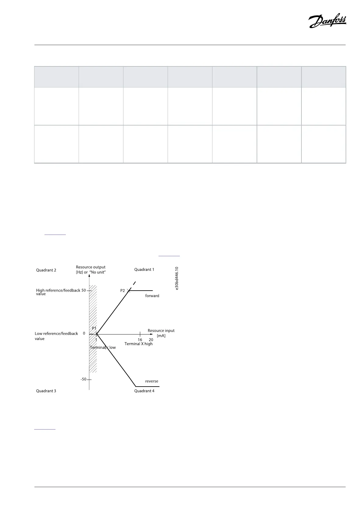
8.3.2.5 Dead Band Around Zero
Sometimes, the reference (in rare cases also the feedback) should have a dead band around 0 to ensure that the machine is stopped
when the reference is near 0.
To make the dead band active and to set the amount of dead band, do the following:
l Set either the minimum reference value or maximum reference value at 0. In other words, either P1 or P2 must be on the X-axis in
Figure 43.
l Ensure that both points defining the scaling graph are in the same quadrant.
P1 or P2 defines the size of the dead band as shown in Figure 43.
Figure 43: Size of Dead Band
Case 1: Positive reference with dead band, digital input to trigger reverse, part I
Figure 44 shows how reference input with limits inside minimum to maximum limits clamps.
Danfoss A/S © 2024.01 AJ435824192086en-000101 / 130R1295 | 83

 Loading...


