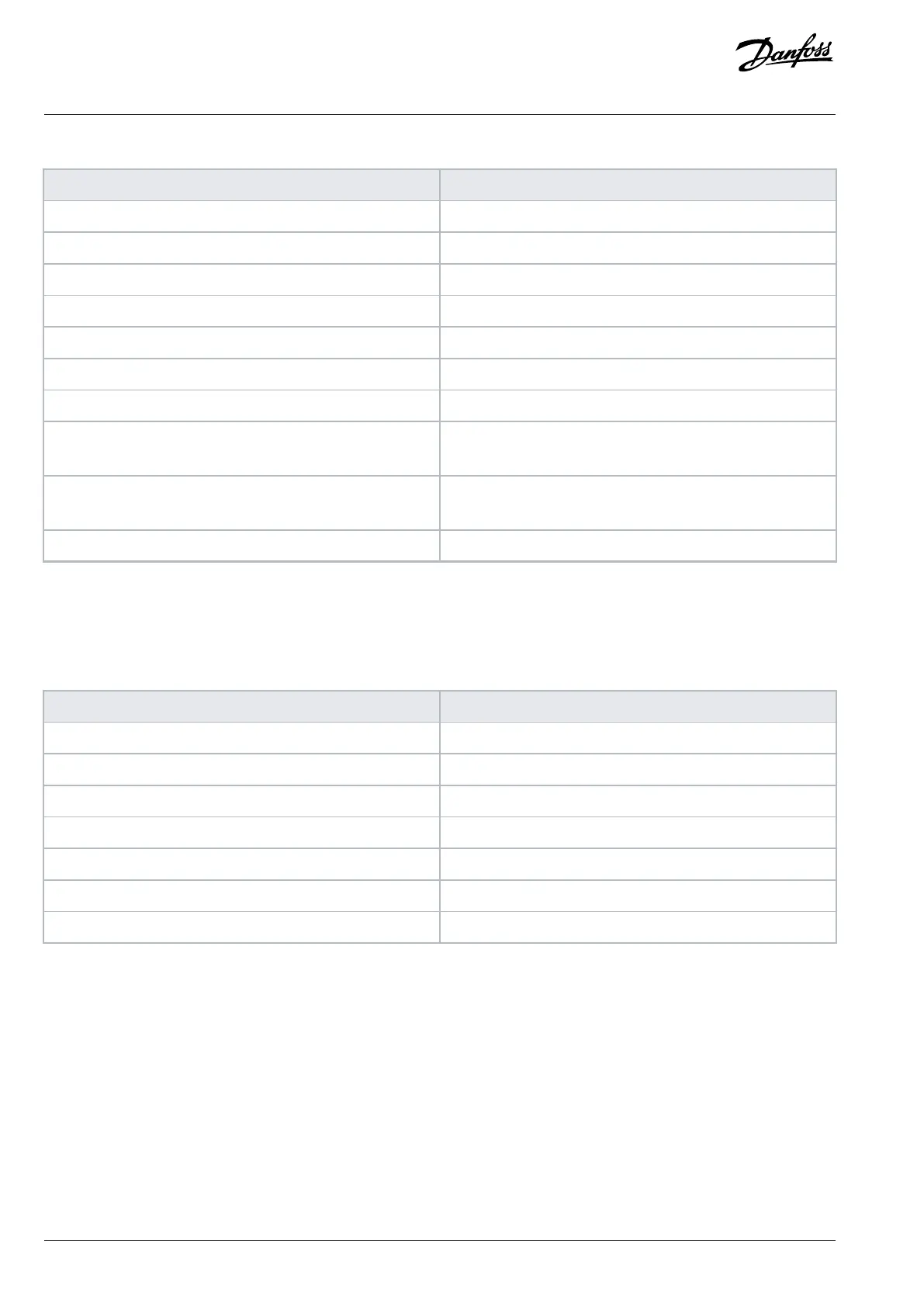
Table 54: Query
Field name Example (hex)
Follower address 01 (drive address)
Function 0F (write multiple coils)
Coil address HI 00
Coil address LO 10 (coil address 17)
Quantity of coils HI 00
Quantity of coils LO 10 (16 coils)
Byte count 02
Force data HI
(Coils 8–1)
20
Force data LO
(Coils 16–9)
00 (reference = 2000 hex)
Error check (CRC) –
Response
The normal response returns the follower address, function code, starting address, and quantity of coils forced.
Table 55: Response
Field name Example (hex)
Follower address 01 (drive address)
Function 0F (write multiple coils)
Coil address HI 00
Coil address LO 10 (coil address 17)
Quantity of coils HI 00
Quantity of coils LO 10 (16 coils)
Error check (CRC) –
9.10.5 Read Holding Registers (03 hex)
Description
This function reads the contents of holding registers in the follower.
Query
The query telegram specifies the starting register and quantity of registers to be read. Register addresses start at 0, that is, registers 1–4
are addressed as 0–3.
Example: Read parameter 3-03 Maximum Reference, register 03030.
110 | Danfoss A/S © 2024.01 AJ435824192086en-000101 / 130R1295
Design Guide | VLT® AutomationDrive FC 360

 Loading...


