5.8 Analog Inputs
Number of analog inputs 2
Terminal number 53, 54
Modes Voltage or current
Mode select Software
Voltage level 0–10 V
Input resistance, Ri Approximately 10 kΩ
Maximum voltage -15 V to +20 V
Current level 0/4 to 20 mA (scaleable)
Input resistance, Ri Approximately 200 Ω
Maximum current 30 mA
Resolution for analog inputs 11 bit
Accuracy of analog inputs Maximum error 0.5% of full-scale
Bandwidth 100 Hz
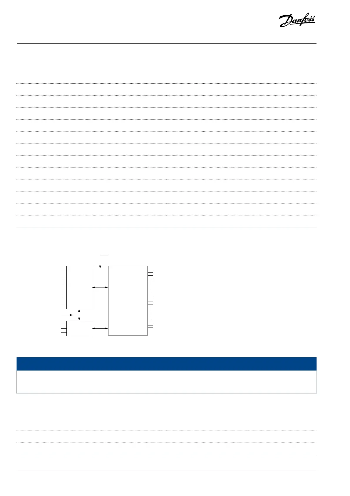
The analog inputs are galvanically isolated from the supply voltage (PELV) and other high voltage terminals.
PELV isolation
Motor
DC Bus
High
voltage
Control
Figure 7: Analog Inputs
NOTICE
HIGH ALTITUDES
l For installation at altitudes above 2000 m (6562 ft), contact Danfoss regarding PELV.
5.9 Pulse Inputs
Programmable pulse inputs 2
Terminal number pulse 29, 33
Maximum frequency at terminal 29, 33 (push-pull driven) 32 kHz
30 | Danfoss A/S © 2024.01 AJ435824192086en-000101 / 130R1295
Design Guide | VLT® AutomationDrive FC 360

 Loading...


