Design Guide | VLT® AutomationDrive FC 360
Maximum speed limit
Parameter 4-14 Motor Speed High Limit [Hz] or parameter 4-19 Max Output Frequency sets the maximum output speed that the drive
can provide.
ETR (electronic thermal relay)
The drive ETR function measures the actual current, speed, and time to calculate motor temperature. The function also protects the
motor from being overheated (warning or trip). An external thermistor input is also available. ETR is an electronic feature that simulates a
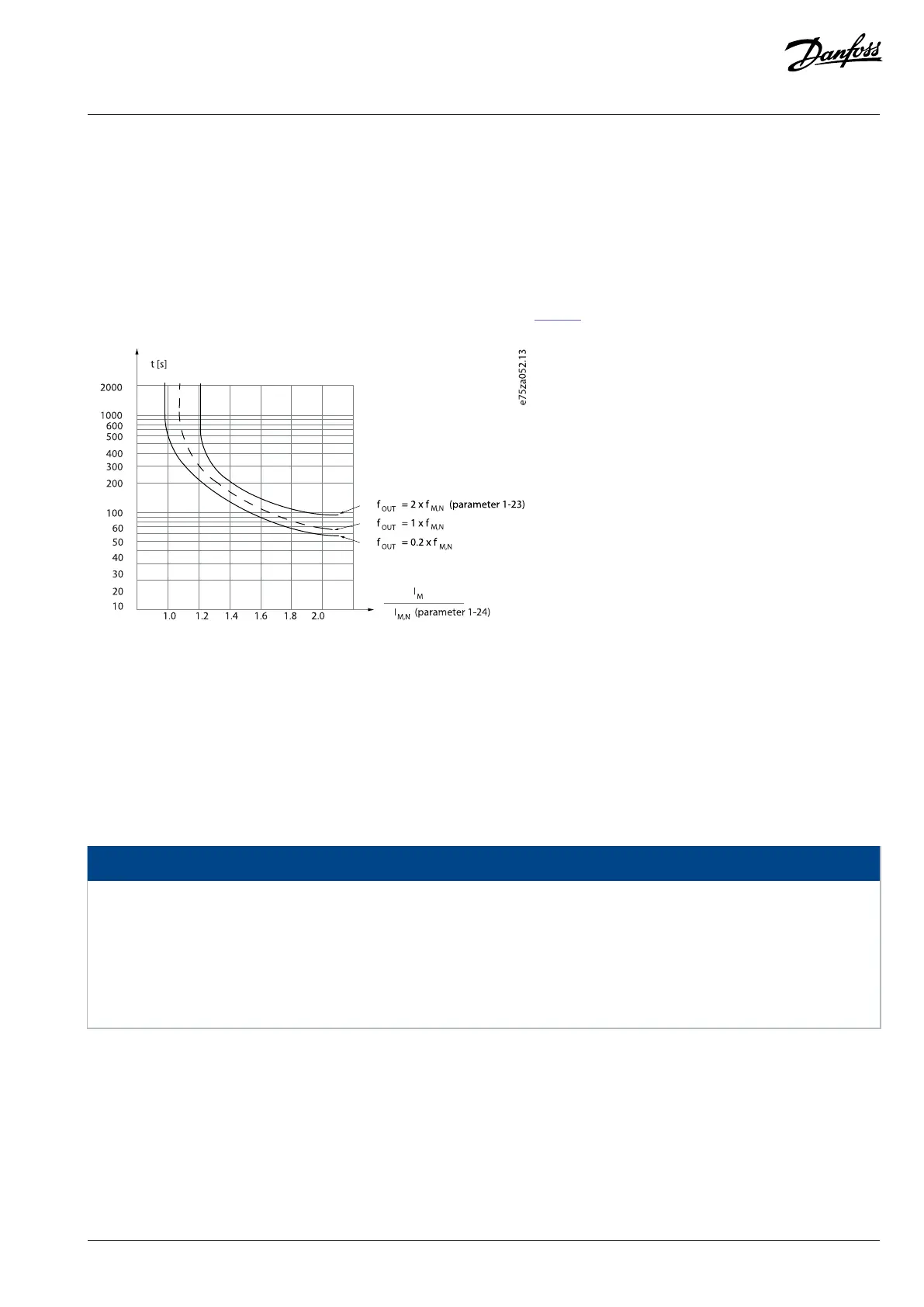
bimetal relay based on internal measurements. The characteristic is shown in Figure 1.
Figure 1: ETR
The X-axis shows the ratio between I
motor
and I
motor
nominal. The Y-axis shows the time in seconds before the ETR cuts off and trips the
drive. The curves show the characteristic nominal speed at twice the nominal speed and at 0.2 x the nominal speed.
At lower speed, the ETR cuts off at lower heat due to less cooling of the motor. In that way, the motor is protected from being overheated
even at low speed. The ETR feature calculates the motor temperature based on actual current and speed. The calculated temperature is
visible as a readout parameter in parameter 16-18 Motor Thermal.
The motor ETR function is based on NEMA thermal relay function Class 10.
NOTICE
The drive contains a software ETR function, which means that the drive has no information about what happens with the motor at
different ambient temperatures and/or what happens at 1000 m above sea level. The software ETR function cannot fully replace
a thermistor relay, because the thermistor relay includes a PTC sensor mounted on the motor, which is controlling the relay.
However, the software ETR function is flexible and takes different parameters into account to get the required results. Besides the
software ETR function, the drive has other protection features, for example, current limit and inverter thermal. In many situations,
these features protect the drive and motor against overloads.
3.3.5 Mains Dropout
During a mains dropout, the drive keeps running until the DC-link voltage drops below the minimum stop level. The minimum stop level
is typically 15% below the lowest rated supply voltage. The mains voltage before the dropout and the motor load determine how long it
takes for the drive to coast.
The drive can be configured (parameter 14-10 Mains Failure) to different types of behavior during mains dropout:
l Trip lock once the DC-link is exhausted.
Danfoss A/S © 2024.01 AJ435824192086en-000101 / 130R1295 | 19

 Loading...


