Design Guide | VLT® AutomationDrive FC 360
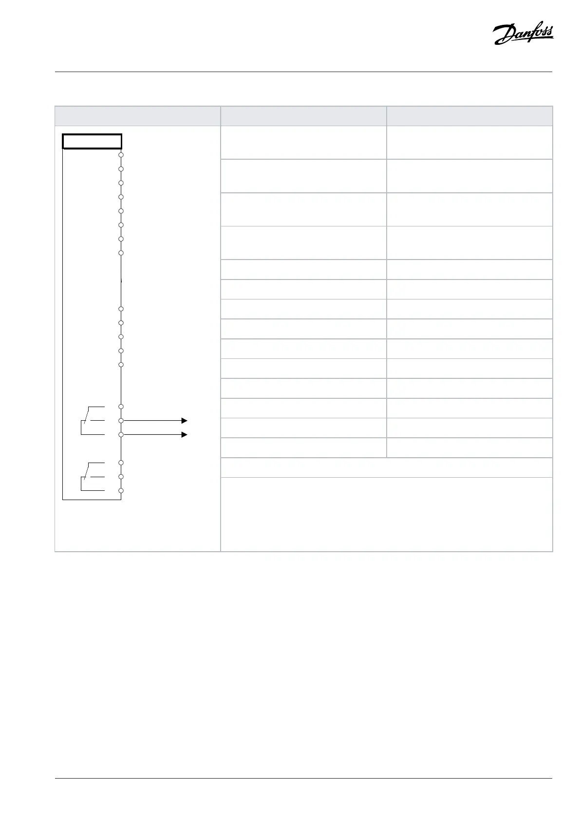
Table 74: Using SLC to Set a Relay
Parameter function Parameter setting
Parameter 4-30 Motor Feedback Loss
Function
[1] Warning
Parameter 4-31 Motor Feedback Speed
Error
100
Parameter 4-32 Motor Feedback Loss
Timeout
5 s
Parameter 7-00 Speed PID Feedback
Source
[2] MCB 102
Parameter 17-11 Resolution (PPR) *1024
Parameter 13-00 SL Controller Mode [1] On
Parameter 13-01 Start Event [19] Warning
Parameter 13-02 Stop Event [44] Reset key
Parameter 13-10 Comparator Operand [21] Warning no.
Parameter 13-11 Comparator Operator *[1]≈
Parameter 13-13 Comparator Value 90
Parameter 13-51 SL Controller Event [22] Comparator 0
Parameter 13-52 SL Controller Action [32] Set digital out A low
Parameter 5-40 Function Relay [80] SL digital output A
*=Default value
33
31
50
53
54
55
42
01
02
03
04
05
06
e30bd150.12
Notes/comments:If the limit in the feedback monitor is exceeded, warning 90 feedback
monitor is issued. The SLC monitors warning 90 feedback monitor. If warning 90 feed-
back monitor becomes true, relay 1 is triggered. External equipment could indicate that
service is required. If the feedback error goes below the limit again within 5 s, the drive
continues and the warning disappears. But relay 1 persists until [Off/Reset] is pressed.
10.7 Encoder Connection
The purpose of this guideline is to ease the setup of encoder connection to the drive. Before setting up the encoder, the basic settings for
a closed loop speed control system are shown.
Danfoss A/S © 2024.01 AJ435824192086en-000101 / 130R1295 | 127

 Loading...


