Design Guide | VLT® AutomationDrive FC 360
When using parallel motor connection, observe the following points:
l Run applications with parallel motors in U/F mode (volts per hertz).
l VVC+ mode can be used in some applications.
l Total current consumption of motors must not exceed the rated output current IINV for the drive.
l Problems can occur at start and at low RPM if motor sizes are widely different because the relatively high ohmic resistance in the
stator of a small motor demands a higher voltage at start and at low RPM.
l The electronic thermal relay (ETR) of the drive cannot be used as motor overload protection. Provide further motor overload
protection by including thermistors in each motor winding or individual thermal relays.
l Recommended to run applications with parallel motors in U/F mode parameter 1-01 Motor Control Principle[0] Asynchron. Set the
U/F graph in parameter 1-55 U/f Characteristic - U and parameter 1-56 U/f Characteristic - F.
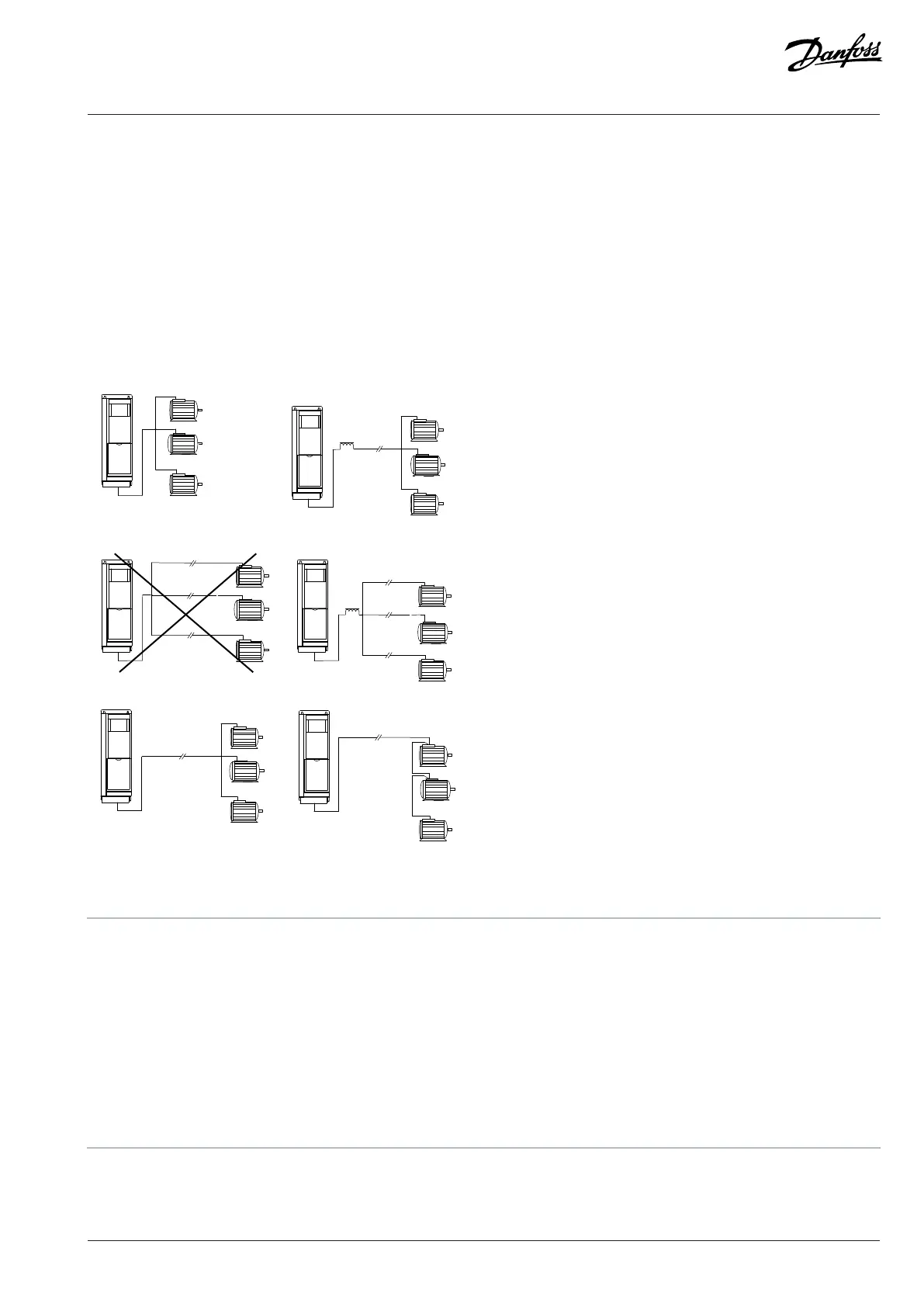
Figure 27: Different Parallel Connections of Motors
A Installations with cables connected in a common joint as shown in A and B are only recommended for short cable lengths.
B Be aware of the maximum motor cable length specified in the chapter Cable Lengths and Cross-sections.
C The total motor cable length specified in the chapter Cable Lengths and Cross-sections is valid as long as the parallel cables are
kept less than 10 m (32 ft) each.
D Consider voltage drop across the motor cables.
E Consider voltage drop across the motor cables.
F The total motor cable length specified in the chapter Cable Lengths and Cross-sections is valid as long as the parallel cables are
kept less than 10 m (32 ft) each.
Danfoss A/S © 2024.01 AJ435824192086en-000101 / 130R1295 | 59

 Loading...


