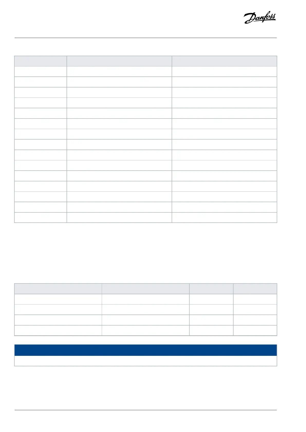
Table 62: Control Word According to FC Profile
Bit Bit value=0 Bit value=1
00 Reference value External selection lsb
01 Reference value External selection msb
02 DC brake Ramp
03 Coasting No coasting
04 Quick stop Ramp
05 Hold output frequency Use ramp
06 Ramp stop Start
07 No function Reset
08 No function Jog
09 Ramp 1 Ramp 2
10 Data invalid Data valid
11 Relay 01 open Relay 01 active
12 Relay 02 open Relay 02 active
13 Parameter setup Selection lsb
15 No function Reverse
Explanation of the control bits
Bits 00/01
Bits 00 and 01 are used to select among the 4 reference values, which are preprogrammed in parameter 3-10 Preset Reference according
to the following table.
Table 63: Control Bits
Programmed reference value Parameter Bit 01 Bit 00
1 Parameter 3-10 Preset Reference [0] 0 0
2 Parameter 3-10 Preset Reference [1] 0 1
3 Parameter 3-10 Preset Reference [2] 1 0
4 Parameter 3-10 Preset Reference [3] 1 1
NOTICE
In parameter 8-56 Preset Reference Select, define how bit 00/01 gates with the corresponding function on the digital inputs.
Bit 02, DC brake
Bit 02 = 0: Leads to DC brake and stop. Set braking current and duration in parameter 2-01 DC Brake Current and parameter 2-02 DC
Braking Time.
114 | Danfoss A/S © 2024.01 AJ435824192086en-000101 / 130R1295
Design Guide | VLT® AutomationDrive FC 360
 Loading...


