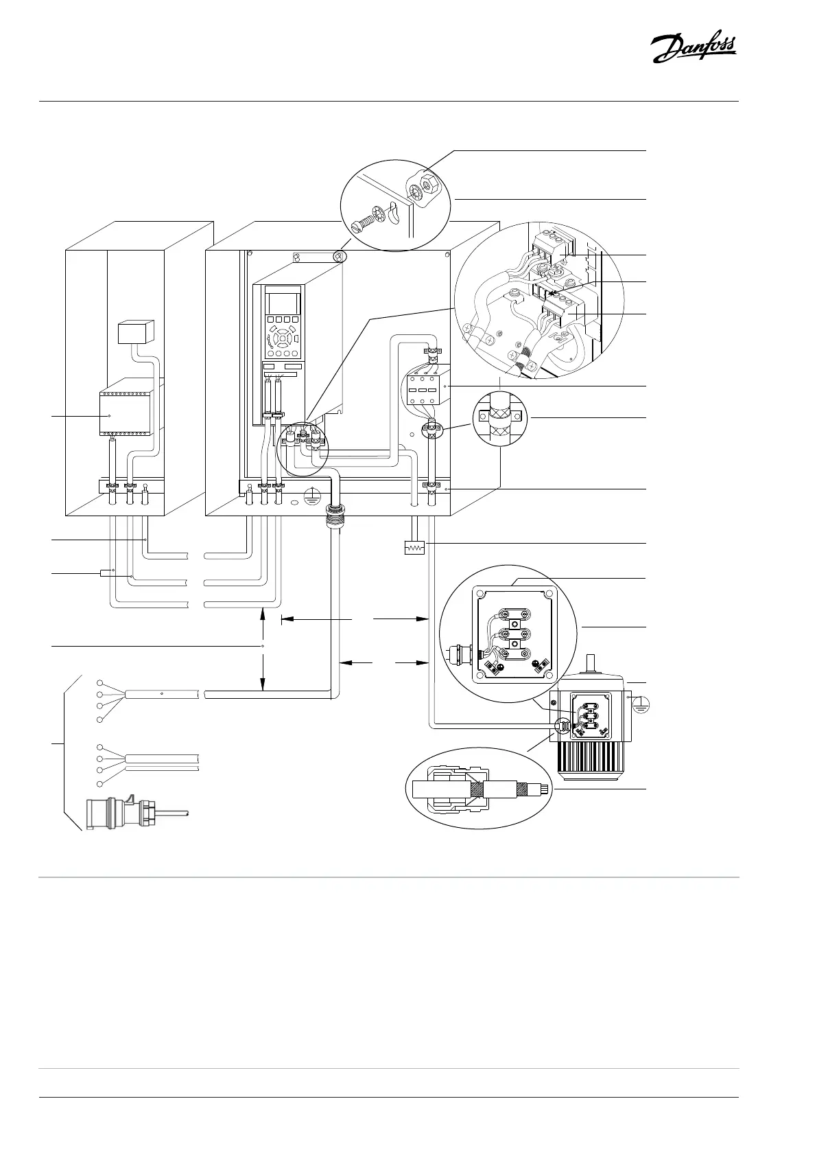
Figure 35: Example of Proper EMC Installation
1 PLC 2
Minimum 16 mm
2
(6 AWG) equalizing cable
3 Control cables 4 Minimum 200 mm (7.9 in) between control cables, motor
cables, and mains cables.
5 Mains supply 6 Bare (unpainted) surface
7 Star washers 8 Brake cable (shielded)
9 Motor cable (shielded) 10 Main cable (shielded)
11 Output contactor 12 Cable insulation stripped
72 | Danfoss A/S © 2024.01 AJ435824192086en-000101 / 130R1295
Design Guide | VLT® AutomationDrive FC 360

 Loading...


