INSTALLATION
3
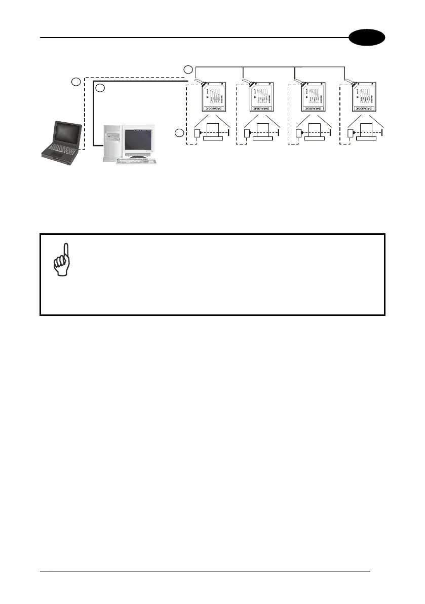
4
Device#n
Master
Device#1
Device#2
2
1
Terminal
Host
3
Main Serial Interface (RS232 or RS485 Full-Duplex or RS485 Half-
Duplex)
Auxiliary Serial Interface (Local Echo) (RS232)
External Trigger (for On-Line Mode)
ID-NET™ (up to 32 devices, max network extension of 1000 m)
Figure 39 – ID-NET™ M/S Multidata
NOTE
The auxiliary serial interface of the slave scanners can be used in
Local Echo communication mode to control any single scanner
(visualize collected data) or to configure it using the Genius™ utility
or Genius™ based Host Mode programming procedure.
The termination resistors of the RS485 bus must be installed inside the
first and last C-BOX.
53

 Loading...