DS2400N
3
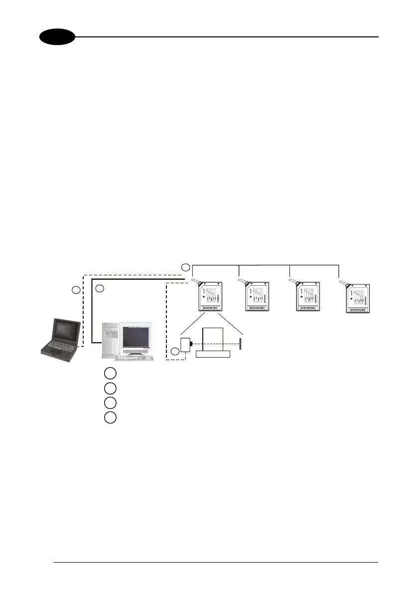
3.6.4 ID-NET™
The RS485 ID-NET™ connection is used to collect data from several scanners to
build a multi-point or a multi-sided reading system; there can be one master and up
to 32 slaves connected together.
The slave scanners are connected together using RS485 half-duplex on the
ID-NET™ interface. Every slave scanner must have a multidrop address in the range
0-31.
The master scanner is also connected to the Host on the RS232/RS485 main serial
interface.
The External Trigger signal is unique to the system; there is a single reading phase
and a single message from the master scanner to the Host computer.
It is not necessary to bring the External Trigger signal to all the scanners.
The main and auxiliary ports are connected as shown in the figure below.
Terminal
Host
2
1
3
4
Master
Slave#1
Slave#2 Slave#n
1
2
3
Main Serial Interface (RS232 or RS485 Full-Duplex or RS485 Half-Duplex)
uxiliary Serial Interface (Local Echo) (RS232)
External Trigger (for On-Line mode)
4
ID-NET™ (up to 16 devices, max network extension of 100 m)
Figure 38 – ID-NET™ M/S Synchronized Layout
52

 Loading...