DS2400N
3
3.3 ELECTRICAL CONNECTIONS
All DS2400N models are equipped with a cable terminated by a 25-pin female D-sub
connector for connection to the power supply and input/output signals.
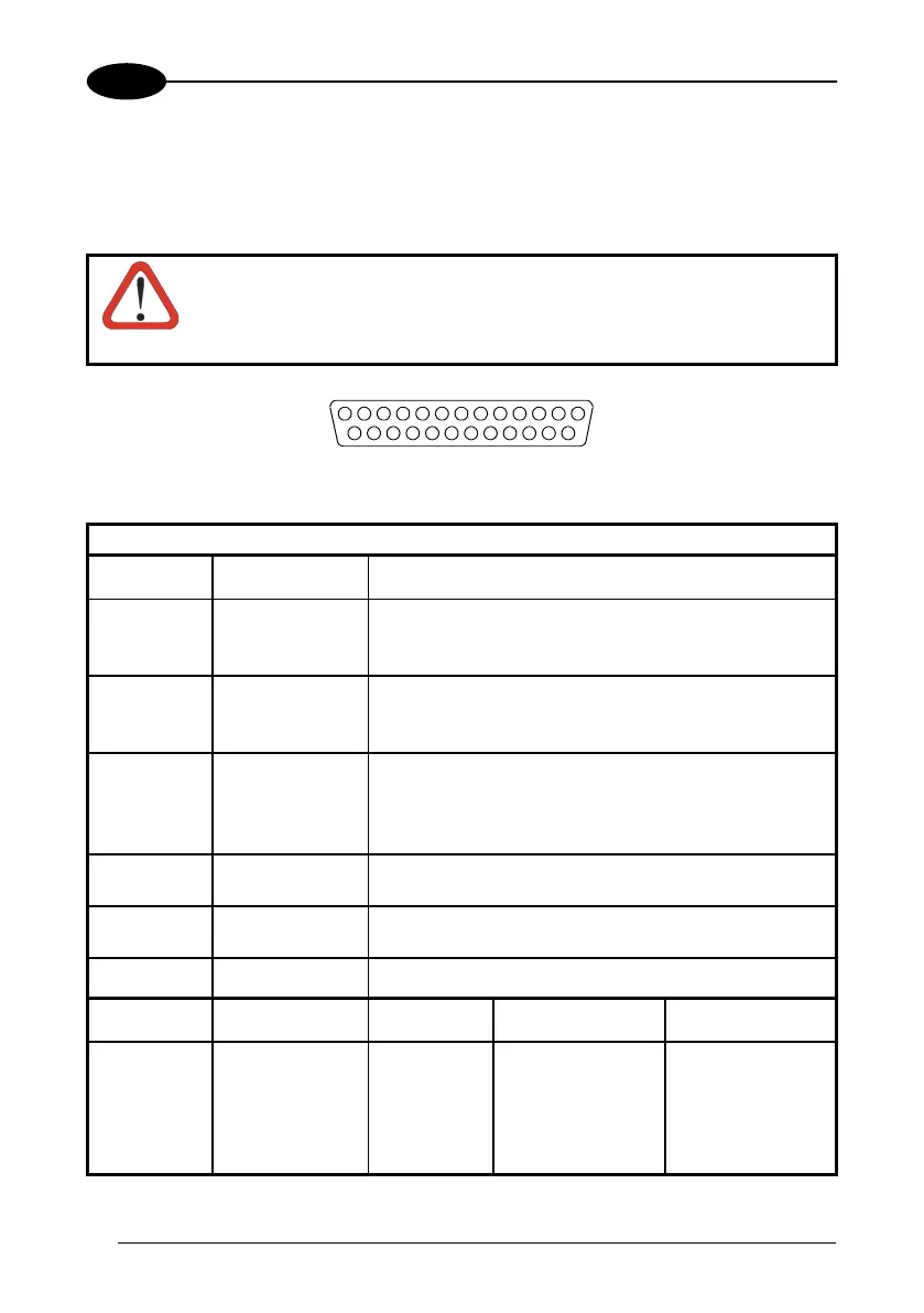
The details of the connector pins are indicated in the following table:
CAUTION
Do not connect GND and SGND to different (external) ground
references. GND and SGND are internally connected through
filtering circuitry which can be permanently damaged if subjected to
voltage drops over 0.8 Vdc.
13 1
14
25
Figure 16 - 25-pin Female D-sub Connector
25-pin D-sub female connector pinout
Pin Name Function
13, 9 VS Power supply input voltage +
25 GND Power supply input voltage -
1 CHASSIS Cable shield connected to chassis
18 EXT TRIG A External Trigger A (polarity insensitive)
19 EXT TRIG B External Trigger B (polarity insensitive)
10 IN2 - Input 2 -
8 OUT1 + Output 1 +
22 OUT1 - Output 1 -
11 OUT2 + Output 2 +
12 OUT2 - Output 2 -
20 RXAUX Auxiliary RS232
21 TXAUX Auxiliary RS232
23 ID-NET + High speed internal network +
24 ID-NET - High speed interconnection network -
6, 10, 14, 15,
16, 17
NC Not Connected
Pin Name RS232
RS485
Full-Duplex
RS485
Half-Duplex
2 TX232 TX485+ RTX485+
3 RX232 RX485+
4 RTS232 TX485- RTX485-
5 CTS232 RX485-
7
MAIN INTERFACE
(SW SELECTABLE)
SGND SGND SGND
30

 Loading...