DS2400N
3
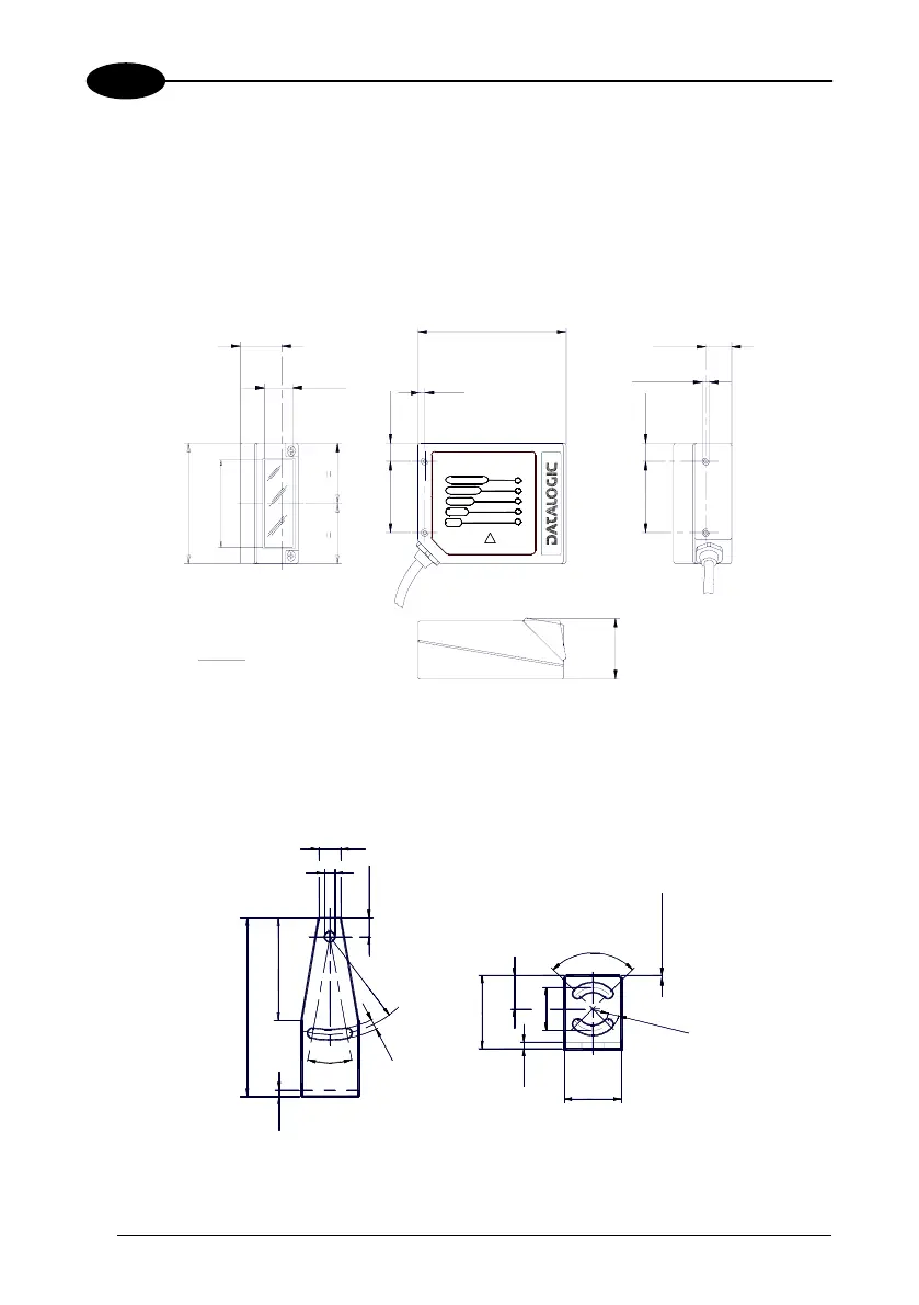
3.2 MECHANICAL INSTALLATION
DS2400N can be installed to operate in different positions. The four screw holes (M4
x 5) on the body of the reader are for mechanical fixture (Figure A, 3). The diagrams
below give the overall dimensions of the scanner and mounting bracket and may be
used for installation.
Refer to par. 3.5 for correct positioning.
23.3*
0.92
14
0.55
84
3.31
4
0.16
10.3
0.41
40
1.57
0.41
10.3
40
1.57
14.7
0.58
M 4 n° 4
1.29
32.7
mm
inch
68
2.68
46
1.81
F4
F3
F2
F1
F0
READY
GOOD
TRIGGER
COM
STATUS
DS2400N
X
PRESS
®
INTERFACE
* The quote refers to the scan line
Figure 11 – DS2100N Overall Dimensions
9
4.2
7.8
20°
2.5
73
42
R
4
0
4
.
2
90°
30
13.8
17.5
2.5
23
mm
4
.
2
n
°
2
1 x 45° n° 2
Figure 12 – Mounting Bracket Overall Dimensions
26

 Loading...