FUNCTIONS
56
SAFERY LASER SCANNER
Stand Alone model: 6 Zone Sets
In order to make the device monitor six different areas, the user must configure the
Zone Sets page to define and assign input signal combinations to “Area Switch” inputs
and check that the switching equipment that generates the sequence does not violate
any combination states according to the Switching State Map shown below.
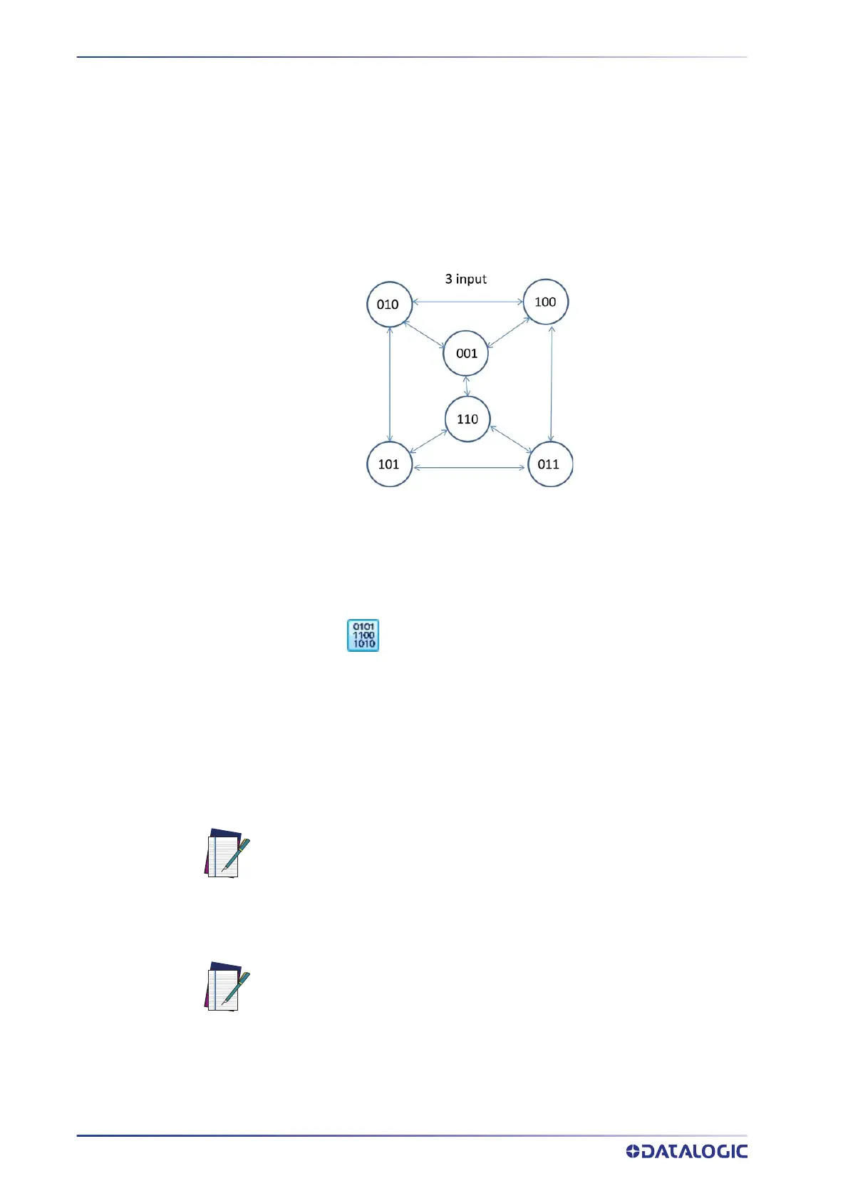
The following diagram shows the valid Zone Set state switching. Any sequence not con-
nected by an arrow is not valid. For example, a Zone Set assigned 011 cannot switch to a
Z
one Set assigned 001. This would violate the requirement that at least two Area Switch
inputs change signal levels from one zone to the next. Any such implementation will
cause the Laser Sentinel to go into fault state (lockout).
Figure 2 - Switching State Map
1. Set the Zone Set No. to “6”. Six Zone Sets will appear with their relative Area
Switch combinations.
2. Assign a univocal combination to the Area Switches. The easiest way is to use the
binar
y coding icon to automatically set the input combinations. Example:
Zone Set 1: Area Switch 1 = 0 Area Switch 2 = 1 Area Switch 3 = 0
Zone Set 2: Area Switch 1 = 1 Area Switch 2 = 0 Area Switch 3 = 0
Zone Set 3: Area Switch 1 = 0 Area Switch 2 = 1 Area Switch 3 = 1
Zone Set 4: Area Switch 1 = 1 Area Switch 2 = 0 Area Switch 3 = 1
Zone Set 5: Area Switch 1 = 1 Area Switch 2 = 1 Area Switch 3 = 0
Zone Set 6: Area Switch 1 = 0 Area Switch 2 = 0 Area Switch 3 = 0
NOTE
3. Assign each Area Switch to an available Input Signal Pin.
NOTE
The combinations 000 and 111 are not allowed.
The Stand Alone Laser Sentinel has three configurable Inputs. If the user
chooses to employ from three to six Zone Sets there will be no available I/
O for other functions. For example, it will not be possible to employ the
Manual Restart or send an electrical warning signal.

 Loading...