Scada
128
5.8.4 GOVERNOR/AVR INTERFACE
NOTE: These settings are not stored in the module configuration. They are stored in a different
memory area and not transferred with the configuration. The Clone Module feature transfers both the
configuration AND the settings of the Multiset, Governor/AVR interface and the Sync page.
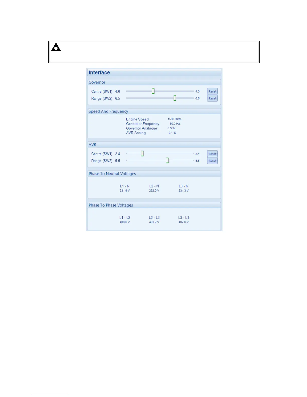
SW1 and SW2 are the configurable settings for the analogue governor output and analogue AVR output
included on the DSE8810 controller.
As the input requirements of governors and AVRs vary from manufacturer to manufacturer, and even from
model to model, the DSE module is configurable to allow connection to many devices.
The analogue governor and AVR outputs are both isolated from ground and battery negative, allowing
compatibility with devices with inputs that are not referenced to ground or battery negative.
5.8.4.1 SW1
SW1 is also known as Centre. SW1 sets the voltage produced by the DSE module’s output for ‘nominal’. For
example SW1 = 2 for the governor output, means that the analogue governor output will be 1.0V DC when the
engine is required to run at it’s nominal speed.
5.8.4.2 SW2
SW2 is also known as Range. SW2 sets the range of the ‘swing’ around the Centre (SW1) voltage produced
by the DSE module’s output for change. For example SW2 = 2 for the governor output, means that the
analogue governor output will be made to change by up to 1.5V DC either side of the Centre (SW1) voltage to
make the engine run at lower or higher speeds or to increase/decrease load share.
 Loading...