5.0V
Typical wiring diagrams and SW1/SW2 selector settings for many of the most popular governors are included
within the DSE guide to synchronising and Load Sharing (Part2).
5.8.4.4 SUMMARY
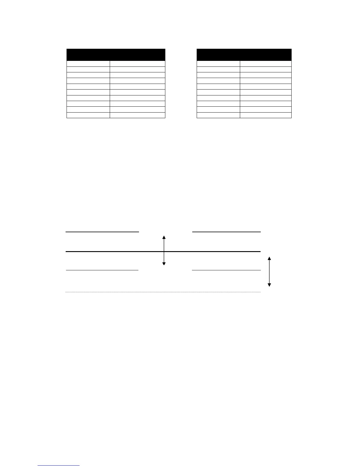
You can think of the settings as Analogue output voltage is SW1 ± SW2
In the example above this means the analogue output is 1.0V ± 1.5V (based upon the settings of SW1=2 and
SW2=2
SW1 is the voltage above (or below) 0V that the analogue output will produce to instruct ‘no change’ to the
voltage/frequency of the genset.
SW2 is the maximum voltage above (and below) SW1 that the analogue output will produce to instruct the
voltage/frequency of the genset to change.
0V DC
SW1 (Centre)
SW2 (Range)
SW2 (Range)
 Loading...