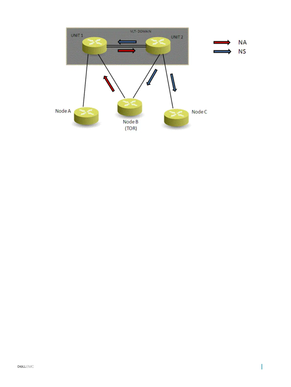
Figure 133. Sample Conguration of IPv6 Peer Routing in a VLT Domain
Sample Conguration of IPv6 Peer Routing in a VLT Domain
Consider a sample scenario as shown in the following gure in which two VLT nodes, Unit1 and Unit2, are connected in a VLT domain using
an ICL or VLTi link. To the south of the VLT domain, Unit1 and Unit2 are connected to a ToR switch named Node B. Also, Unit1 is connected
to another node, Node A, and Unit2 is linked to a node, Node C. The network between the ToR and the VLT nodes is Layer 2. Servers or
hosts that are connected to the ToR (Node B) generate Layer 3 control/data trac from the South or lower-end of the vertically-aligned
network.
Virtual Link Trunking (VLT)
941

 Loading...