Chapter 4 Parameters|
Revision August 2008, 03VE, SW V2.04 4-27
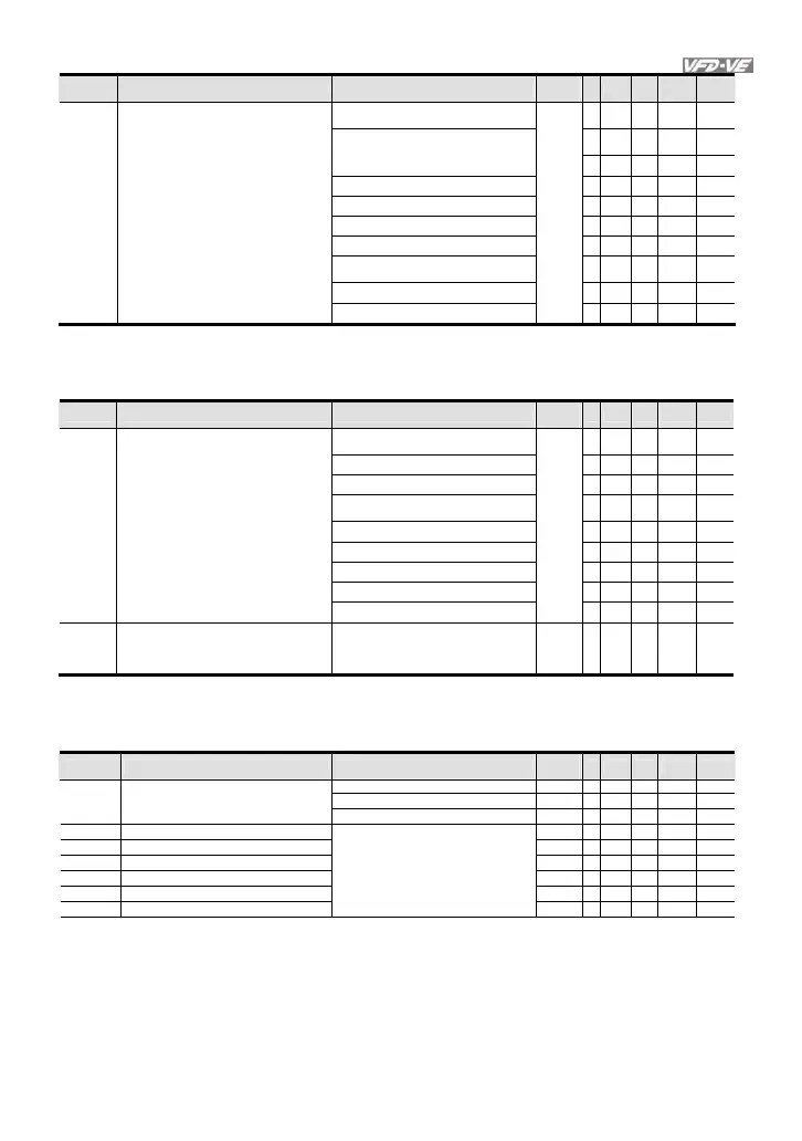
Pr. Explanation Settings
Factory
Setting
VF
VFPG
SVC
FOCPG
TQRPG
02-35
Multi-function Output 5 (MO3) 33: Zero speed (actual output
frequency)
○ ○ ○ ○
02-36
Multi-function Output 6 (MO4) 34: Zero speed with Stop (actual output
frequency)
○ ○ ○ ○
02-37
Multi-function Output 7 (MO5) 35: Error output selection 1 (Pr.06-23)
○ ○ ○ ○ ○
02-38
Multi-function Output 8 (MO6) 36: Error output selection 2 (Pr.06-24)
○ ○ ○ ○ ○
02-39
Multi-function Output 9 (MO7) 37: Error output selection 3 (Pr.06-25)
○ ○ ○ ○ ○
02-40
Multi-function Output 10 (MO8) 38: Error output selection 4 (Pr.06-26)
○ ○ ○ ○ ○
02-41
Multi-function Output 11 (MO9) 39: Position attained (Pr.10-19)
○
02-42
Multi-function Output 12 (MOA) 40: Speed attained (including zero
speed)
○ ○ ○ ○
41: Multi-position attained
○
42: Crane function
○ ○ ○ ○
Group 3 Analog Input/Output Parameters
In version 2.02, the parameters are from Pr.03-00 to Pr.03-20. The settings for Pr.03-00 to
Pr.03-02 are from 0 to 10
Pr. Explanation Settings
Factory
Setting
VF
VFPG
SVC
FOCPG
TQRPG
03-00
Analog Input 1 (AVI) 2: torque command (torque limit under
speed mode)
0
○
3: Torque compensation command
○ ○ ○ ○ ○
03-01
Analog Input 2 (ACI) 4: PID target value (refer to group 8)
○ ○ ○ ○
5: PID feedback signal (refer to group
8)
○ ○ ○ ○
03-02
Analog Input 3 (AUI) 6: P.T.C. thermistor input value
○ ○ ○ ○ ○
7: Positive torque limit
○
8: Negative torque limit
○
9: Regenerative torque limit
○
10: Positive/negative torque limit
○
03-20
Analog Output Value in REV Direction 0: Absolute value in REV direction
1: Output 0V in REV direction
2: Enable output voltage in REV
direction
0
○ ○ ○ ○ ○
Group 6 Protection Parameters
In version 2.02, the parameters are from Pr.06-00 to Pr.06-31. The settings of Pr.06-01 are
shown as follows. The settings for Pr.06-17 to Pr.06-22 are from 0 to 62.
Pr. Explanation Settings
Factory
Setting
VF
VFPG
SVC
FOCPG
TQRPG
0.0: Disable
350.0~450.0Vdc 380.0
○ ○ ○ ○ ○
06-01
Over-voltage Stall Prevention
700.0~900.0Vdc 760.0
○ ○ ○ ○ ○
06-17 Present Fault Record 0
○ ○ ○ ○ ○
06-18 Second Most Recent Fault Record 0
○ ○ ○ ○ ○
06-19 Third Most Recent Fault Record 0
○ ○ ○ ○ ○
06-20 Fourth Most Recent Fault Record 0
○ ○ ○ ○ ○
06-21 Fifth Most Recent Fault Record 0
○ ○ ○ ○ ○
06-22 Sixth Most Recent Fault Record
0: No fault
1: Over-current during acceleration
(ocA)
2: Over-current during deceleration
(ocd)
3: Over-current during constant speed
(ocn)
0
○ ○ ○ ○ ○

 Loading...


