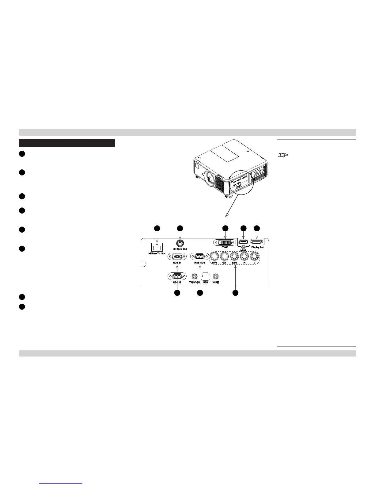
Signal Inputs And Outputs
1
HDBaseT
Receives digital input from HDBaseT-compliant
devices.
2
3D Sync Out
Sync output signal. This may be affected by the 3D
Sync Invert setting in the CONTROL > 3D menu.
Connect this to your IR emitter or ZScreen.
3
DVI-D
Connect a DVI-D cable to the DVI connector.
4
HDMI
HDMI 1.4 input. Connect an HDMI cable to the
connector.
5
DisplayPort
DisplayPort 1.2 input. Connect a DisplayPort cable to
the connector.
6
RGB In
Receives analog signal from a computer. When using
this input, it is best to use a fully wired VGA cable to
connect the source to the projector. This will allow the
source to determine the projector’s capabilities via DDC
and show an optimized image.
Such cables can be identied as they have a blue
connector shell.
Use the INPUT > VGA Setup menu.
7
RGB Out
8
Component
RGBHV, RGsB or RGBS
• Set Color Space in the INPUT menu to Auto or
RGB-Video.
YPbPr or YCbCr
• Set Color Space in the INPUT menu to YPbPr or
YCbCr.
Notes
For a complete listing of pin
congurations for all signal and
control connectors, see Wiring
Details later in this Guide.
1 2 3 4 5
6 7 8
 Loading...