DisplayPort
DisplayPort 1.2
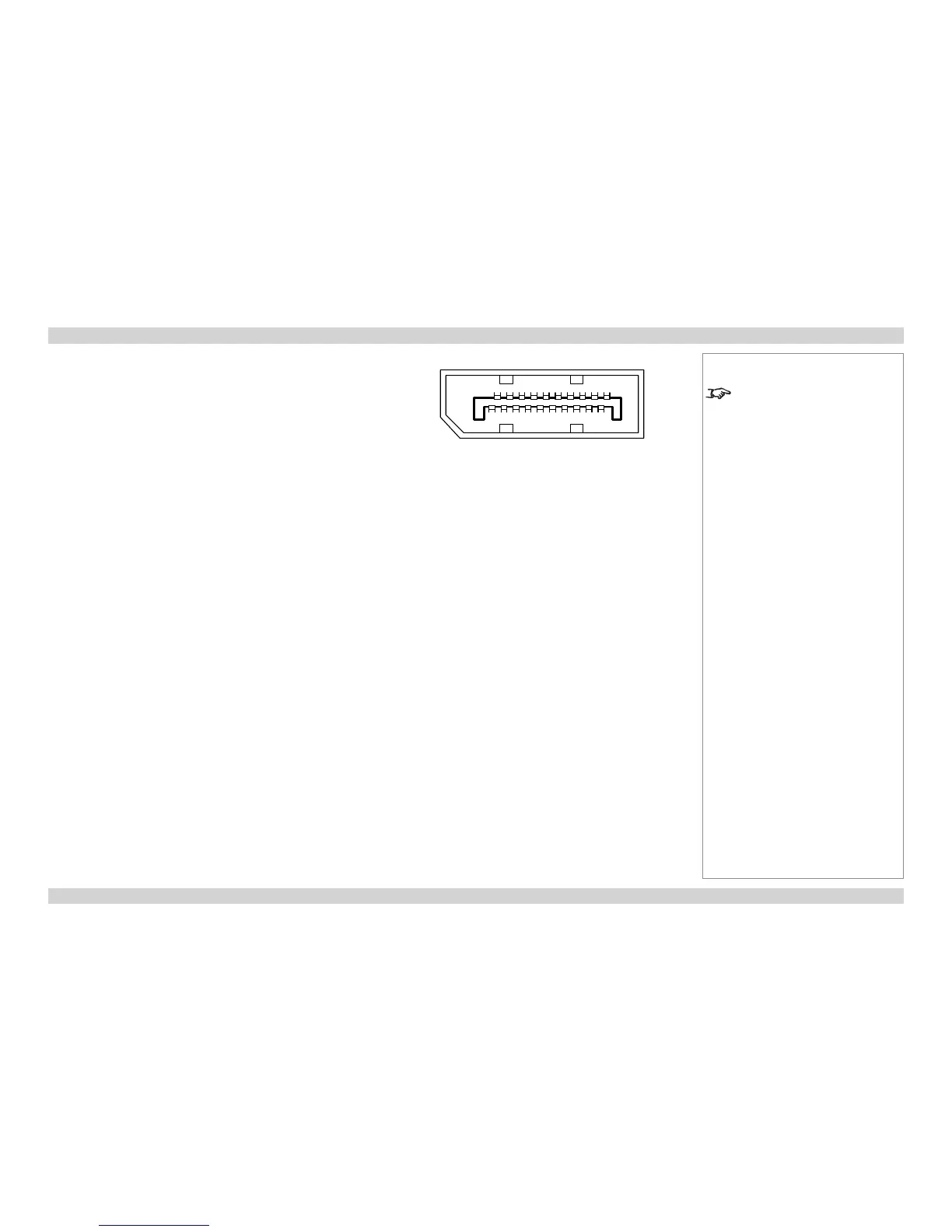
Pin 1 ML_Lane 0 (p) Lane 0 (positive)
Pin 2 GND Ground
Pin 3 ML_Lane 0 (n) Lane 0 (negative)
Pin 4 ML_Lane 1 (p) Lane 1 (positive)
Pin 5 GND Ground
Pin 6 ML_Lane 1 (n) Lane 1 (negative)
Pin 7 ML_Lane 2 (p) Lane 2 (positive)
Pin 8 GND Ground
Pin 9 ML_Lane 2 (n) Lane 2 (negative)
Pin 10 ML_Lane 3 (p) Lane 3 (positive)
Pin 11 GND Ground
Pin 12 ML_Lane 3 (n) Lane 3 (negative)
Pin 13 CONFIG1 connected to Ground1)
Pin 14 CONFIG2 connected to Ground1)
Pin 15 AUX CH (p) Auxiliary Channel (positive)
Pin 16 GND Ground
Pin 17 AUX CH (n) Auxiliary Channel (negative)
Pin 18 Hot Plug Hot Plug Detect
Pin 19 Return Return for Power
Pin 20 DP_PWR Power for connector (3.3 V 500 mA)
Notes
For full details of all input settings,
see the INPUT menu in the
Operating Guide.
19111517
19
13 7 5 3
21012161820 14 8 6 4
pin view of connector
 Loading...