DOBOT CR5 User Guide 5 Function Description of Software
Issue V3.5.3.1 (2020-05-09) User Guide Copyright © Yuejiang Technology Co., Ltd
48
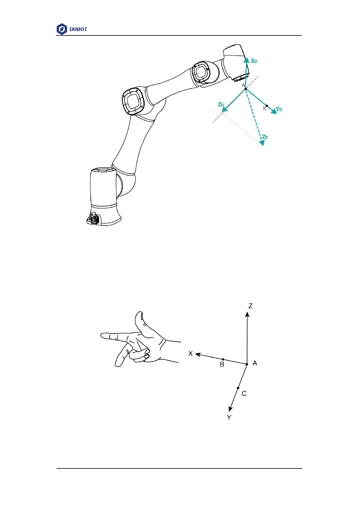
Figure 5.8 Line
Area: User coordinate system is created by three-point calibration method. Move the robot
to three points A(x1, y1, z1), B(x2, y2, z2), and C(x3, y3, z3). Point A is defined as the origin
and the line from point A to Point B is defined as the positive direction of X-axis. The line that
point C is perpendicular to X-axis is defined as the position direction of Y-axis. And then the
Z-axis can be defined based on the right-handed rule, as shown in Figure 5.9.
Figure 5.9 Area