DOBOT CR5 User Guide 5 Function Description of Software
Issue V3.5.3.1 (2020-05-09) User Guide Copyright © Yuejiang Technology Co., Ltd
49
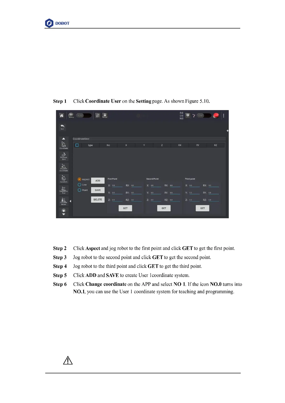
Take the establishment of User 1 coordinate system as an example.
Prerequisites
The robot has been powered on.
The APP has been in the manual mode.
The robot is enabled.
The robot is in the Cartesian coordinate system.
Procedures
Figure 5.10 User coordinate system
5.1.1.4 Setting Tool Coordinate System
When an end effector such as welding gun, gripper is mounted on the robot, the Tool coordinate
system is required for programming and operating a robot. For example, you can use multiple
grippers to carry multiple workpieces simultaneously to improve the efficiency by setting each
gripper to a Tool coordinate system.
There are totally 10 groups of Tool coordinate systems. Tool 0 coordinate system is the
predefined Tool coordinate system which is located at the robot flange and cannot be changed.
NOTICE