■■■■■■■■■■■■■■■■■■■■■■■■■■■■■■■■■■■■■■■■■■■■■■■■■■■■■■■■■■■■■■■■■■■■■■■■■■■■■■■■■■■■■■■■■■■■■■■■■
▼
Mapping of I/O Signals
DS1103 Hardware Installation and Configuration March 2004
205
▲
■■■■■■■■■■I
▲■■■■■■■■■■■■■■■
GND of the DS1103 is internally connected to PC ground.
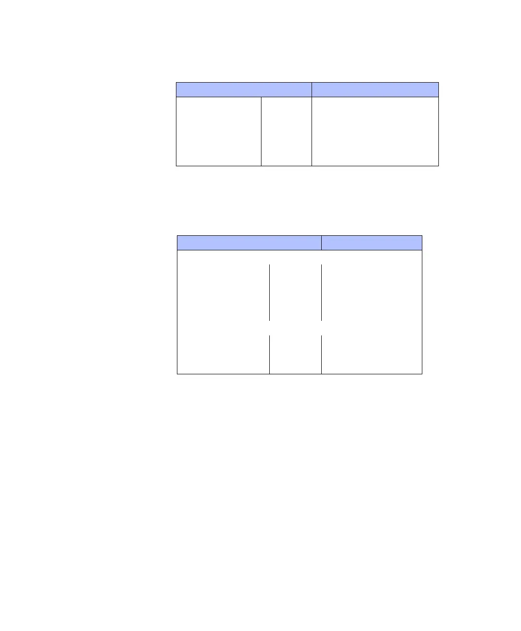
VCC pins The following I/O pins provide access to the PC power supply VCC
(5 V):
N
DS1103 and Sub-D connector The DS1103 provides three VCC
lines. The total load of every VCC line (VCC1, VCC2 or VCC3) must
not exceed 500 mA.
CP1103/CLP1103 connector panels All VCC1, VCC2, and
VCC3 lines of the DS1103 are connected on the CP1103/CLP1103
and called VCC. The total load of all connector pins that provide
access to the PC power supply must not exceed 1.5 A (CP1103) or
0.75 A (CLP1103).
Incremental encoder
iInterface
CP32 … CP37,
CP39
8, 10 … 15
CAN CP38 3, 5, 6
UART RS232 CP40 5
Slave RS232 CP41 5
UART RS422 CP42 5
Slave RS422 CP43 5
Connector Pin
Connector Pin
DS1103
Digital connector P2 • VCC1: 95 … 98
Incremental encoder/
digital connector
P3 • VCC2: 91 … 94
• VCC3: 95 … 98
Sub-D connectors P2A, P2B • VCC1: 17, 33
P3A, P3B • VCC2: 16, 49
• VCC3: 17, 33
CP1103/CLP1103 connector panel
Digital I/O CP30 50
Slave I/O CP31 19
Incremental encoder interface CP32 … CP37,
CP39
1, 9
 Loading...
