Maintenance Manual (960-942) 4-32
Replacement Procedures
4.22 Keyboard/Cover Assembly
The keyboard is assembled to the Cover Assembly by hot melt glue. When
either the keyboard or the Cover Assembly needs to be replaced with a
new one, please replace them all with a new set of keyboard and Cover
Assembly which are already assembled.
4.22.1 Removing the Keyboard/Cover Assembly
To remove the Keyboard/Cover Assembly, follow the step below and refer
to Figure 4-38.
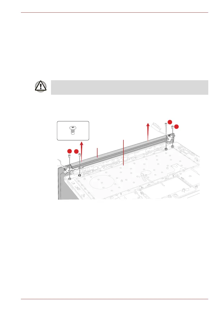
1. Release the following screws and separate the LCD Assembly and
Cover Assembly.
Figure 4-38 Removing the Keyboard/Cover Assembly
4.22.2 Installing the Keyboard/Cover Assembly
To install the Keyboard/Cover Assembly, follow the step below and refer to
Figure 4-38.
1. Set the LCD Assembly on the Cover Assembly and secure them with
the screws.
As the keytop may fall out, when handling the keyboard, always hold it by
the frame and do not touch the key top.
2
1
F2.5x5BT
LCD Assembly
Cover Assembly
3
4
 Loading...