Maintenance Manual (960-942) 4-43
Replacement Procedures
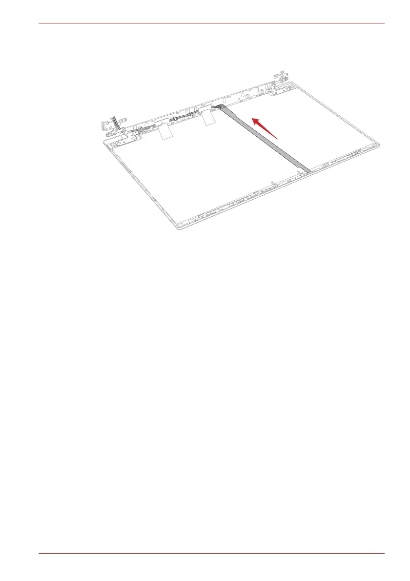
6. Arrange the camera harness to the guides on the LCD cover.
Figure 4-52 Installing the Camera module
4.25 Display hinges
4.25.1 Removing the display hinges
To remove the display hinges, follow the steps below and refer to Figure 4-
53.
1. Release the following screws and remove the left & right hinges.
■ F2.5x3.5BT x2 (Described as “1” in the figure)
■ SH2.5x2.5BT x4 (Described as “2” in the figure)
 Loading...