EasyManuals Logo

EDAN M8 Series User Manual

EDAN M8 Series
206 pages
To Next Page IconTo Next Page
To Previous Page IconTo Previous Page
Page #32 background imageLoading...
Page #32 background image
Patient Monitor User Manual Introduction
- 23 -
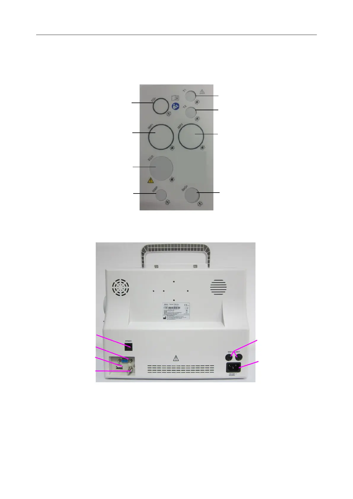
5. TEMP1 probe connector
6. TEMP2 probe connector
7. IBP2 transducer connector
8. SpO
2
sensor connector
Figure 3-9 Left Panel
Rear Panel
Figure 3-10 Rear Panel
Network Interface (reserved): Standard RJ45 Socket, for connecting to MFM-CMS of the
manufacturer.
VGA interface (optional)
USB port
Equipotential grounding terminal for connection with the hospitals grounding system.
Fuse box, in which fuses are put.
1
2
3
4
5
6
7
8

Table of Contents

Questions and Answers:

Question and Answer IconNeed help?

Do you have a question about the EDAN M8 Series and is the answer not in the manual?

EDAN M8 Series Specifications

General IconGeneral
BrandEDAN
ModelM8 Series
CategoryMeasuring Instruments
LanguageEnglish

Related product manuals