Patient Monitor User Manual Introduction
- 14 -
Chapter 3 Introduction
This user manual is based on the maximum configuration and therefore your monitor may not
have all of the functions and options described in the manual. Also, illustrations in this manual
serve as examples only and do not necessarily reflect the setup on your monitor. The content
displayed on you monitor depends on the way it has been tailored for your hospital.
You may frequently use the follow functions:
ECG monitoring (Refer to Chapter 13 Monitoring ECG/RESP for more information.)
SpO
2
monitoring (Refer to Chapter 14 Monitoring SpO
2
for more information.)
TEMP monitoring (Refer to Chapter 16 Monitoring TEMP for details)
NIBP monitoring (Refer to Chapter 15 Monitoring NIBP for more information.)
Alarm (Refer to Chapter 6 Alarms for more information.)
3.1 General Information
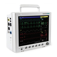
The monitor integrates the functions of parameter measurement module, display, recording and
output to compose a compact, portable device. Its built-in replaceable battery provides
convenience for patient movement. On the high-resolution display screen, 7 waveforms and all
the monitoring parameters can be displayed clearly.
The POWER switch is on the left of the front panel (Figure 3-1 ①). The POWER indicator
lights when the monitor is powered on (Figure 3-1②). The CHARGE indicator shows the
charging status (Figure 3-1). The ALARM indicator flashes when the alarm is triggered (Figure
3-1④). The sockets of various sensors are on the left panel. Other sockets and the power plug-in
are on the rear panel. The recorder is on the right panel.
The monitor is a user-friendly device with operations conducted by a few buttons and a rotary
knob on the front panel (Figure 3-1⑤⑥). Refer to Section 3.3 Button Functions.
 Loading...