47
support@edgeovens.com
Technical Support: +1 (724) 628 3050
INSTALLATION
FINAL CONNECTIONS
GAS
Always check for leaks after making any gas supply piping connections or performing
any service on the oven. Leak testing is required during installation.
WARNING
VALVE SPECIFICATIONS
MAXIMUM INLET PRESSURE: 37 mbar / 14.8 inWC
HEATING CAPACITY: 58.6kW / 200,000 BTU/hr
PRESSURE DROP ACROSS VALVE: 3.7 mbar / 1.5 inWC
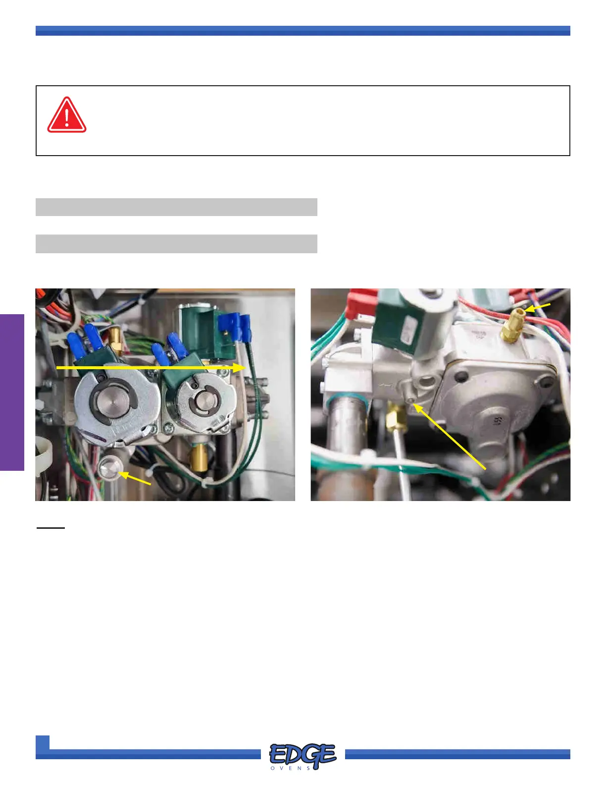
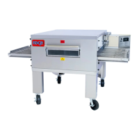
KEY
1. PILOT VALVE
2. MAIN VALVE
3. BYPASS VALVE
4. REGULATOR SPRING
5. MANIFOLD PRESSURE TAP
6. INLET PRESSURE TAP
1 2
3
FLOW DIRECTION
Adjustment of the manifold pressure, via the valve regulator spring, is
generally not required. Manifold pressure is factory adjusted.
The correct setting for the manifold is stated in the section ‘OVEN GAS
SPECIFICATIONS’, in the ‘SPECIFICATION’ section of this manual, or
can be located on the data plate located on the oven control cabinet side
and on the secondary plate located on the inside of the control cabinet.
5
6
4
The INLET PRESSURE TAP (6) allows measurement of the supply or
“curb” pressure in to the gas valve.
The MANIFOLD PRESSURE TAP (5) allows measurement of the manifold
pressure out of the of the gas valve.
The REGULATOR SPRING (4) provides the means to adjust the manifold
pressure.
FIGURE 2-108 FIGURE 2-109