51
support@edgeovens.com
Technical Support: +1 (724) 628 3050
INSTALLATION
AIR SHUTTER CONFIRMATION & ADJUSTMENT
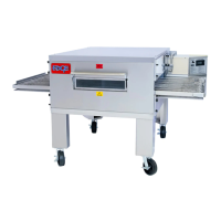
FIGURE 2-124 - TYPE 1
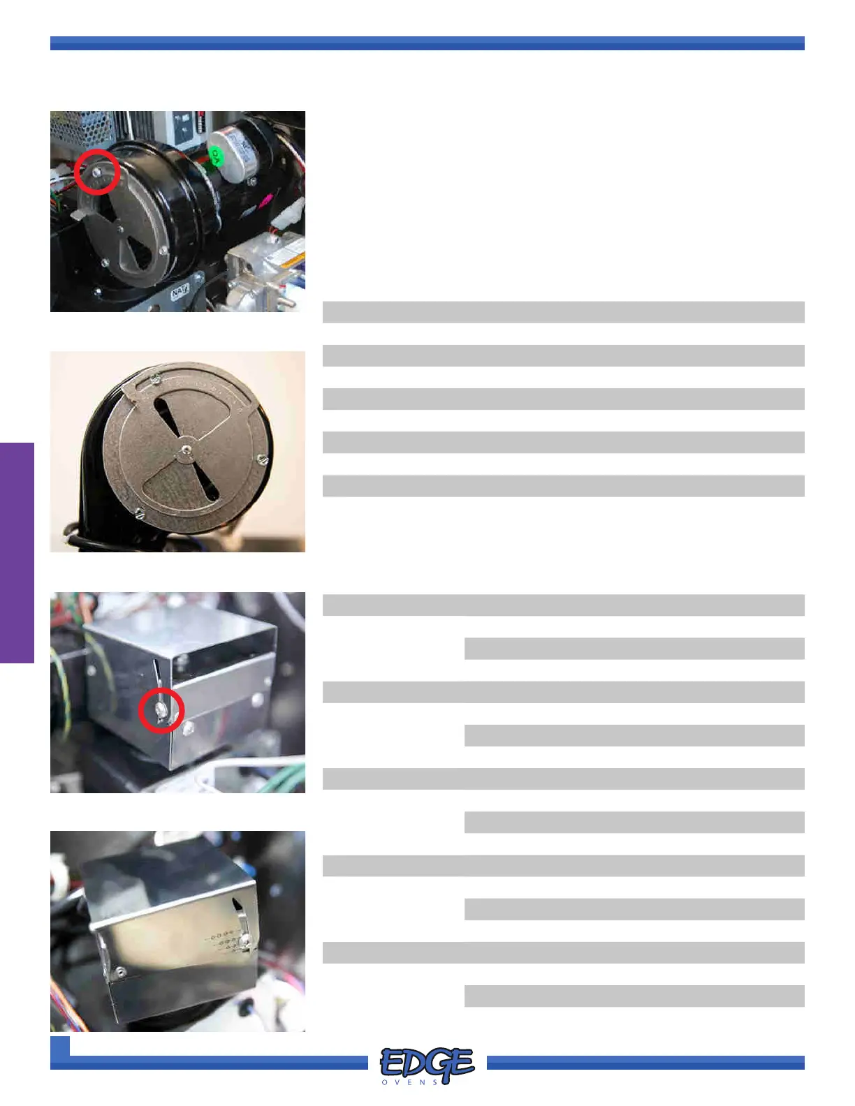
FIGURE 2-123 - TYPE 1
The air shutter allows the correct amount of combustion air to be
drawn into the burner blower and delivered to the burner. The shutter
is to be adjusted to the region specications as below.
To adjust, loosen the securing screw and move shutter up or down
accordingly.
MODEL AIR SHUTTER POSITION AIR SHUTTER POSITION
NATURAL GAS LPG
TYPE 1 TYPE 2 TYPE 1 TYPE 2
1830 1 2 1 3
2440 1.5 2 1 3
3240 1.5 2 1 3
2460 1.5 2 1 3
3260(S) 1.5 2 1 3
3860 1.5 2 1 3
4460 1.5 2 1 3
3270 1.5 2 1 3
3870 1.5 2 1 3
MODEL GAS CATEGORY MANIFOLD
PRESSURE
(MBAR)
AIR SHUTTER
POSITION
(TYPE 2)
1830 I2H / I2E 11.2 2
I2L / I2E+ 17.4 2
I3P / I3+ 24.9 3
I3B / I3B/P 18.7 3
2440 I2H / I2E 11.2 2
I2L / I2E+ 17.4 2
I3P / I3+ 24.9 3
I3B / I3B/P 18.7 3
3240 I2H / I2E 11.2 2
I2L / I2E+ 17.4 2
I3P / I3+ 24.9 3
I3B / I3B/P 18.7 3
2460 / 3260(S) / 3860 I2H / I2E 11.2 2
I2L / I2E+ 17.4 2
I3P / I3+ 24.9 3
I3B / I3B/P 18.7 3
4460(S) / 3270 / 3870 I2H / I2E 11.2 3
I2L / I2E+ 17.4 3
I3P / I3+ 24.9 3
I3B / I3B/P 18.7 3
WORLD MODELS (CE)
US DOMESTIC (120V/60HZ)
FIGURE 2-125 - TYPE 2
FIGURE 2-126 -TYPE 2