There is also a feature that allows a delayed start of the pump. With this feature, the
vent valve can be closed before starng the pump. This allows the backing pump to
decrease the pressure in the vacuum system before starng the pump.
With a ‘Y’ cable adaptor, a TAV and a cooling fan can be controlled at the same me. No
conguraon is necessary.
2.3.6 Normal speed seng
The normal speed is a user‑selectable parameter which can be set from 50% to 100% of
full rotaonal speed.
When the pump gets to normal speed, a signal is available on the normal pin of the logic
interface connector. The signal can be used to control the applicaon as it shows that
the vacuum performance (pump speed) is at a set level. The default seng is 80% of the
full rotaonal speed. Refer to Normal speed seng on page 62 for instrucons to
change the normal speed seng.
2.3.7 Electronic braking
The pump has a user‑selectable electronic braking opon which is disabled by default.
With the electronic braking opon disabled, the pump will take power from the
electrical supply during acceleraon and operaon.
When the pump decelerates it will coast down and power will not be returned to the
electrical supply.
The electronic braking opon can be enabled to decrease the pump deceleraon me
and to recover some energy from the pump. This can be done by returning the power
from the pump to the electrical supply. The rate at which the electrical energy is
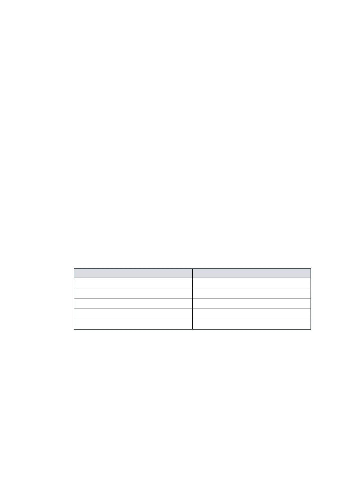
returned to the supply is regulated to the voltages shown:
Voltage range Returned electronic braking voltage
Below 21.6 V d.c. (24 V d.c. -10%) Outside working range for pump
21.6 V d.c. to 26.4 V d.c. 24 V d.c. +10%
26.4 V d.c. to 38.4 V d.c. Electronic braking not funconal
38.4 V d.c. to 50.4 V d.c. 48 V d.c. +10%
Above 50.4 V d.c. (48 V d.c. +5%) Outside working range for pump
To get the fastest electronic braking mes, the returned power must go to somewhere,
such as:
▪
A supply capable to receive the returned power.
▪
Other devices that share the same electrical supply bus with the pump.
▪
An applicable 2 A load during the deceleraon of the pump.
2.4 Logic interface
The pump controller can be operated only through the logic interface. The signals on the
logic interface are of three types:
▪
Control inputs: Switch‑type signals that are used to control the pump
▪
Status outputs: To idenfy the status of the system
Page 14
B8G000880_D - Introducon