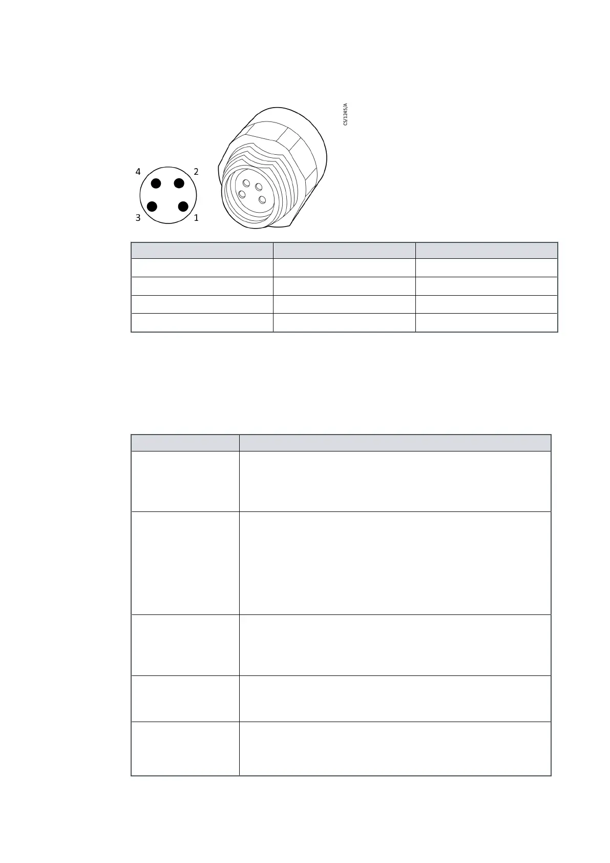
Figure 9 Valve connector
Pin number Signal Polarity
1 0V return Negave
2 Aux output 1 Posive
3 Aux output 2 Posive
4 Chassis Chassis
3.11 Indicator LEDs
The pump has ve indicator LEDs. Refer to Figure: Motor controller status informaon on
page 46.
Table 9
Indicator LEDs
LED Descripon
Normal LED
The green LED comes on when the rotaonal speed of the
pump is more than the normal speed seng, irrespecve of
the acceleraon or deceleraon of the pump. The LED is
duplicated at the sides of the pump.
Status LED
The yellow LED ashes with a 50% duty cycle at the rotaonal
frequency of the pump motor. At high speeds it is connuously
on. The LED sets to o when the rotaonal speed is very low or
stopped. If the next service is available, the LED ashes in a
sequence to show which service operaon is necessary. Refer
to Fault nding on page 86. The LED is duplicated at the sides of
the pump.
Alarm LED
The red LED ashes in a sequence to show an error code if a
FAIL condion is prevenng the pump operaon. The error
codes can be used for the fault nding as given in Fault nding
on page 86. The LED is duplicated at the sides of the pump.
Serial
Communicaons
Receive (Rx) LED
The yellow LED ashes when the acvity is sensed on the serial
link receive line. It can be used for the fault nding the serial
link.
Serial
Communicaons
Transmit (Tx) LED
The yellow LED ashes when the motor controller transmits the
data to the serial link transmit line. It can be used for the fault
nding the serial link.
Page 29
B8G000880_D - Technical data