The soware in the pump can operate with the other pumps connected to a single serial
link master. This is a mul-drop mode. The RS485 opon is recommended for the mul-
drop mode. When the RS232 opon is selected, more hardware is necessary to link
number of pump units to a single serial link master. A concept drawing of one possible
arrangement is shown in Figure: Conceptual diagram for mul-drop connecon using
RS232 interface on page 53. When the RS485 opon is selected, it is easy to connect
number of pumps to a single master. Refer to Figure: RS485 mul-drop connecon on
page 54.
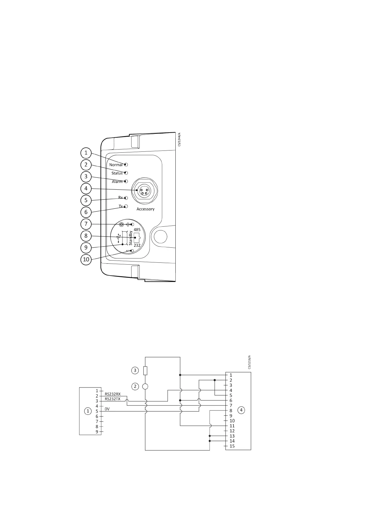
Figure 15 Motor controller status informaon
1. Normal LED 2. Status LED
3. Alarm LED 4. Accessory connector
5. Serial receive LED 6. Serial transmit LED
7. Standby speed increase buon 8. RS232 / RS485 slide switch
9. USB connector 10. Standby speed decrease buon
1. Normal LED 2. Status LED
3. Alarm LED 4. Accessory connector
5. Serial receive LED 6. Serial transmit LED
7. Standby speed increase buon 8. RS232 / RS485 slide switch
9. USB connector 10. Standby speed decrease buon
Figure 16 Logic interface connecons - RS232 serial control
1. RS232 interface on control equipment 2. 24 ‑ 48 V d.c. electrical supply
3. Fuse 4. nEXT pump logic interface
1. RS232 interface on control equipment 2. 24 ‑ 48 V d.c. electrical supply
3. Fuse 4. nEXT pump logic interface
Page 46
B8G000880_D - Installaon