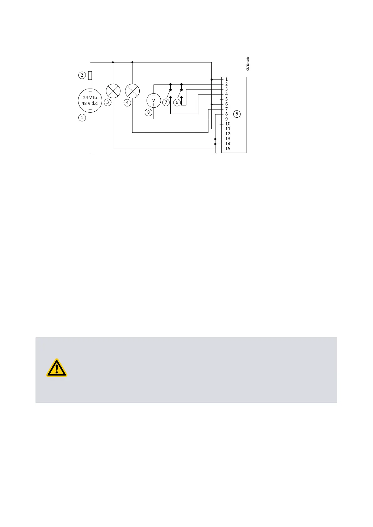
Figure 14 Logic interface connecons - parallel control
1. 24 - 48 V d.c. electrical supply 2. Fuse
3. Oponal indicator - normal speed 4. Oponal indicator - system OK
5. nEXT pump logic interface 6. Start switch
7. Oponal standby switch 8. Oponal voltmeter to monitor analogue
output
1. 24 - 48 V d.c. electrical supply 2. Fuse
3. Oponal indicator - normal speed 4. Oponal indicator - system OK
5. nEXT pump logic interface 6. Start switch
7. Oponal standby switch 8. Oponal voltmeter to monitor analogue
output
4.6 Connecon for serial control and monitoring
In the serial interface, the pump is controlled through a number of serial commands or
the nST PC soware. You can also check the operaonal status in the serial interface. In
the mul-drop mode, connecon of more than one pump to a single serial port on the
control system is possible.
4.6.1 Connect the serial interface to the customer control equipment
The serial interface is available in RS485 or RS232 opons. Use the slide switch (given
adjacent to the main power lead) to select the serial interface (refer to Figure: Motor
controller status informaon on page 46). To adjust the slide switch, use a small tool to
toggle the slide switch. The default seng of the motor controller is RS232 serial
interface. Replace the round seal to make sure the pump stays IP rated.
CAUTION: PUMP GROUND CONNECTION
Risk of damage to equipment. When you connect the pump to a PC, the 0 V pin on
the RS232 connector can be connected to the ground through the PC. Make sure that
the 0 V rail of the 24 ‑ 48 V d.c. supply is not connected to the ground at other point
(example, at the power supply). If the 0 V rail of the 24 ‑ 48 V d.c. supply will not be
connected to the ground at the PC, use an opto-isolated interface to the PC.
The pump can connect to the RS485 or RS232 serial input on the control equipment or a
PC as shown in Figure: Logic interface connecons - RS232 serial control on page 46 and
Figure: Logic interface connecons - RS485 serial control on page 47. In given
conguraon, the PC is the serial link master and the pump is the slave. The distance
over which the serial link will work is dependent on the dierence in voltage between
the 0 V at the sending and receiving end. If the 0 V reference at the receiving end is in
0.3 V of the 0 V control reference pin on the pump control connector, then the serial link
has to be capable to operate at a distance up to 6 m. For longer distances, an interface
circuit external to the pump can be necessary.
Page 45
B8G000880_D - Installaon