3.9 Logic interface connector
The pump has a 15‑way logic interface connector at the end of the logic interface cable.
Use an applicable connector mang half (not supplied) to connect the nEXT pump to the
customer equipment. Refer to the table that follows for the connector mang half type.
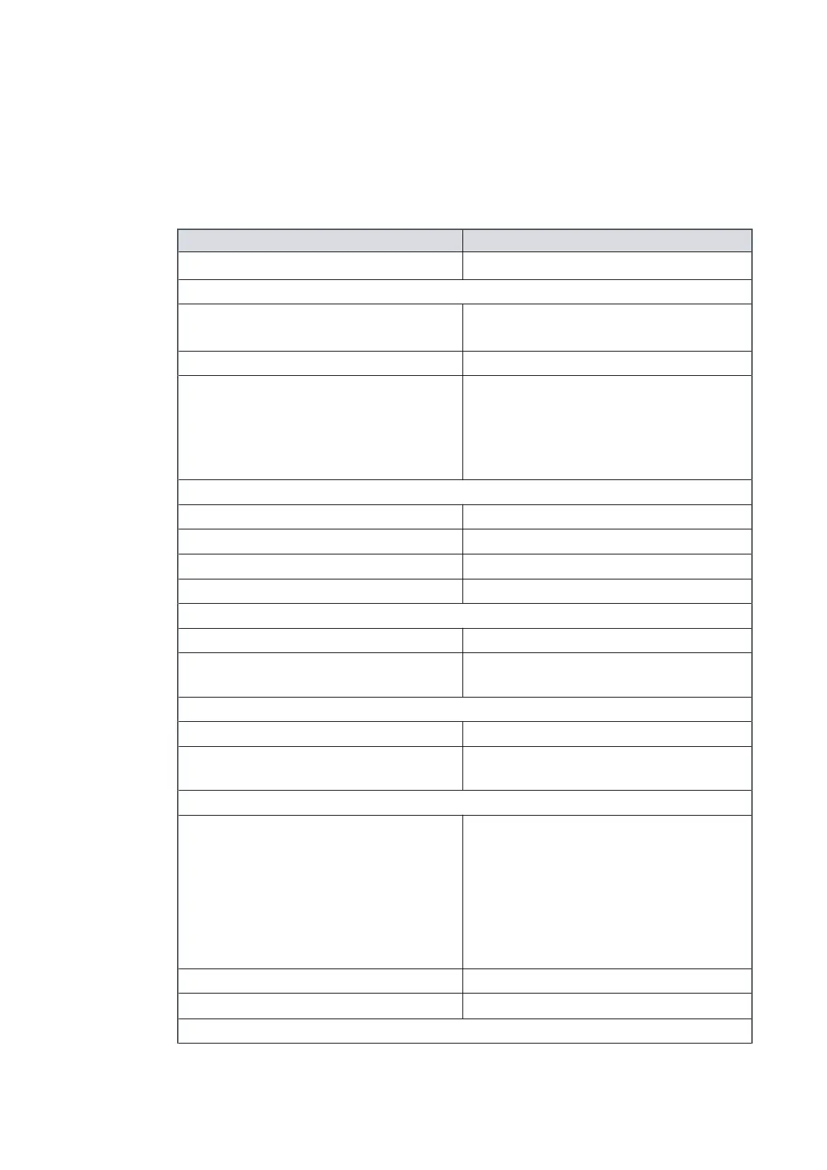
Table 6
Logic interface technical data
Logic interface item
Connector
*
15‑way D‑type male
nEXT pumps electrical supply:
Permied voltage range
(with ripple)
24 V d.c. to 48 V d.c. +5%, -10%
(21.6 to 50.4 V d.c.)
Maximum voltage ripple 0.5 V r.m.s.
Fuse rang T6ALxxxV to T10ALxxxV for 24 V d.c. supply
T4ALxxxV to T10ALxxxV for 48 V d.c.
supply.
Use an IEC/UL/CSA pre-approved fuse
rated ≥ 60 V d.c.
Limit of power supply:
Factory default seng Refer to pump model on a product label
Maximum power limit 120 W
Minimum power limit 50 W
Precision of the power regulaon ± 10 W
Start and serial enable control inputs:
Enabled control voltage: low (close) 0 to 0.8 V d.c. (Iout = 0.55 mA nominal)
Disabled control voltage: high (open) 4 to 26.4 V d.c. (internal pull up to 6.4 V
nominal)
Standby control input:
Enabled control voltage: low (close) 0 to 0.8 V d.c. (Iout = 0.29 mA nominal)
Disabled control voltage: high (open) 4 to 26.4 V d.c. (internal pull up to 3.2 V
nominal)
Analogue output:
Output voltage 0 to 10 V d.c. (directly proporonal to the
measured parameter)
Motor speed: 0 ‑ 1500 Hz (0‑100%)
Motor power: 0 ‑ 120 W
Motor temperature: 0 ‑ 100 °C
Controller temperature: 0 ‑ 100 °C
Rotor temperature: 0 ‑ 100 °C
Voltage precision ± 0.2 V
Output current
£ 5 mA for specied precision
Normal status output:
Page 25
B8G000880_D - Technical data