stop command has been received by the pump can any commands sent through the
parallel interface be acted on.
If you use the start switch on the parallel interface to start the pump, you cannot stop
the pump by sending a stop command over the serial interface. To stop the pump, use
the parallel stop switch. The serial interface accepts the start or stop commands only
when you use the parallel interface switch to stop the pump.
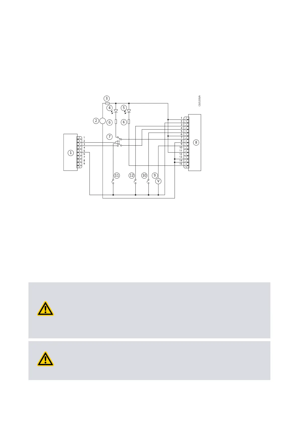
Figure 20 Logic interface connecon - mixed parallel and serial operaon
1. RS232 interface on control equipment 2. 24 V d.c. electrical supply
3. Fuse 4. Oponal LED indicator - system OK
5. Oponal LED indicator - normal speed 6. Current limit resistor for LED
7. Oponal serial link selector 8. pump
9. Oponal voltmeter 10. Oponal serial enable switch
11. Oponal standby switch 12. Start switch
4.8 Cooling
4.8.1 Cooling requirements
CAUTION: PUMP COOLING
Risk of damage to equipment. Make sure that the pump is suciently cooled to
prevent damage to the rotor and bearing.
When you use an alternave conguraon (other than the manufacturer's standard
cooling accessories) to cool the pump, make sure that the cooling is not directed or
ducted onto the pump controller.
CAUTION: VENTILATION FOR PUMP
Risk of damage to equipment. If the pump is in an enclosure, make sure that
sucient venlaon is available. The ambient temperature around the pump must
not be more than 40 °C.
Page 55
B8G000880_D - Installaon