▪ RS485/RS232 switch is in RS232 posion and
▪ parallel standby line is acve.
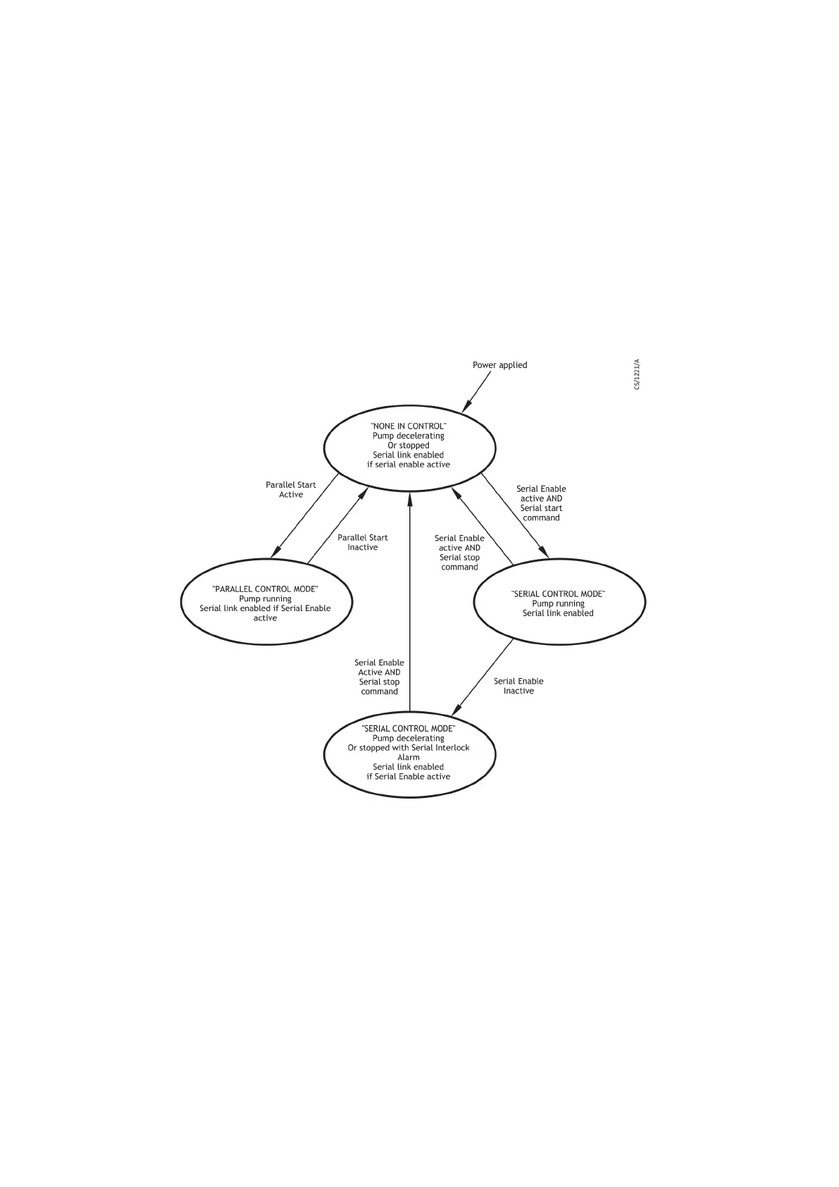
In serial control mode, the state of the parallel Start line will be ignored but the serial
enable line gives an interlock funcon as shown in Figure: Serial and parallel control
owchart on page 77. This interlock funcon only operates with serial start commands
and in serial control mode only. In serial control mode, the pump cannot be commanded
to standby speed by the standby line, instead a serial standby command must be used.
The parallel normal and analogue output signals give valid pump status informaon at all
mes under mixed parallel and serial operaon. The analogue output voltages are given
in Table: Logic interface technical data on page 25.
Figure 22 Serial and parallel control owchart
6.6 Operaon with a TIC or TAG
The pump can be connected to manufacturer's TIC Turbo Instrument Controller, TIC
Turbo Controller or TAG Controller. The TIC gives the power necessary to operate the
pump, but the TAG requires a separate PSU to be connected.
Instrucons on the setup and operaon with the TIC Turbo Instrument Controller, TIC
Turbo Controller or TAG Controller can be found on CD ROM part number P450-00-000,
which is supplied with the TIC or TAG.
6.7 Decelerang and venng
Decelerate the pump before venng.
Page 77
B8G000880_D - Operaon