Do you have a question about the EIM TEC2000 and is the answer not in the manual?
| Brand | EIM |
|---|---|
| Model | TEC2000 |
| Category | Controller |
| Language | English |
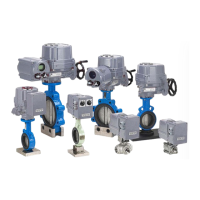
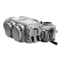
Explains the manual's scope for installing, operating, and maintaining the TEC 2000 valve actuator.
Details precautions to reduce risk of personal injury and equipment damage.
Provides step-by-step instructions for initializing the actuator by setting position limits.
Instructions for configuring network settings for specific ACM and CAM modules.
Verifies actuator operation by checking LED status and valve positions.
Details steps for preparing the stem nut before mechanical installation onto the valve.
Instructions for physically mounting the actuator onto the valve.
Covers procedures for safe removal of the STC cover and initial wiring steps.
Information on installing and using the optional Display Backup Module.
Details actuator control via discrete inputs and power supply connections.
Overview of optional ACM modules for expanding actuator functionality.
Explains power supply connections for analog controlled inputs/outputs.
Wiring details for VFD applications, requiring specific STC configuration.
Requirements and connection details for network control using ACM and CAM.
Instructions for wiring the ARM module, noting it requires factory-trained technicians.
How to connect the RDM, detailing power source options.
Describes the components of the Local Display Module (LDM).
Explains the functions of the LDM's graphics display and message center.
Details the functions of the LDM's control and selector knobs.
Describes the three LEDs on the LDM and their default functions.
Explains how the LDM displays normal activity and status.
Details how the LDM displays status when operating in multi-port valve mode.
Explains that the RDM performs similar functions to the LDM.
Discusses operation priority when both RDMs and LDM are connected.
Describes the infrared controller, its buttons, and functions.
Steps to initialize the actuator, including checking motor rotation.
Procedures for setting initial position limits before actuator operation.
Information on default configuration settings for the TEC 2000 actuator.
Procedures for controlling the actuator locally via LDM or RDM.
Specific steps for local control operation of multi-port valves.
How the actuator can be controlled remotely via discrete inputs and other modes.
Steps to enter the actuator's setup mode for configuration.
Explains how to set or change valve position limits.
Instructions for changing the display language and contrast.
How to transfer files to/from the actuator using a computer.
Minimum system requirements for transferring files.
Installation steps for connecting a computer for file transfer.
How to view various parameters of the actuator.
Overview of changing various actuator settings.
Steps for entering the passcode to change settings.
Configuration options for valve control modes.
Detailed procedure for setting valve travel limits for normal operation.
Configuration of discrete inputs for remote control.
Configuration of relay outputs for status feedback.
Configuration of control inhibits and emergency shut down (ESD) settings.
Configuration of timers for opening and closing times.
Setup for analog control, applicable when Futronic ACM is installed.
Setup for network control, requiring CAM and Controlinc ACM.
Procedure for setting up a tag name for the actuator.
Procedure for changing the actuator's passcode.
How to restore factory default settings.
Common actuator problems and their corrective actions.
How to retrieve and review historical data for troubleshooting.
How to view the last nine alarms that have occurred.
How to view torque data recorded at 10% intervals of valve travel.
How to view stored torque data from the "CHANGE SETTINGS" mode.
How to view operation data accumulated since the last reset.
How to view operation data from initial commissioning.
How to view the status of modules and identify potential hardware faults.
General statement on the low maintenance requirement of the actuators.
Information on lubricants used and their minimal requirement.
Procedure for installing a relief vent fitting on the gearbox.
Instructions for replacing transformer primary fuses in the STC.
Steps for replacing the battery in the infrared controller.