5. Customizing Actuator Settings
TEC 2000 Installation & Operation Manual E2K-405-0902
5-15
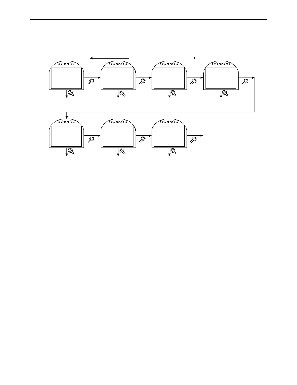
Figure 5-9 Discrete Input Setup
Goto next display
see Figure 5-4
DISCRETE
INPUT
SETUP?
DI #1 ACTIVE
ON CLOSED
CONTACT
NO
YES
DI #2 ACTIVE
ON CLOSED
CONTACT
NO
YES
DI #3 ACTIVE
ON OPEN
CONTACT
NO
YES
BACK NEXT
YES
NO
DI #4 ACTIVE
ON CLOSED
CONTACT
DI #5 ACTIVE
ON CLOSED
CONTACT
NO
YES
DI #6 ACTIVE
ON OPEN
CONTACT
NO
YES
YES
NO
Configuration of discrete inputs are shown below.
DI #3 ACTIVE ON
CLOSED CONTACT
DI #2 ACTIVE ON
OPEN CONTACT
DI #1 ACTIVE ON
OPEN CONTACT
Goto next display
see Figure 5-4
DI #4 ACTIVE ON
OPEN CONTACT
DI #5 ACTIVE ON
OPEN CONTACT
DI #6 ACTIVE ON
CLOSED CONTACT
5.6.5. Discrete Output Setup
Relay outputs are used primarily for hardwired status feedback. Each relay may be
configured (assigned) to various status, alarm, or control functions. Relay outputs can be
configured to be active on the listed alarms/conditions. Relay outputs #1 through #5 are
standard and may be configured as shown in Table 5-2. Configurable functions are listed in
Table 5-3.
To configure the relays:
1. At the “DISCRETE OUTPUT SETUP?” prompt answer “YES.”
2. Use the selector knob (NEXT/BACK) to review the settings for Discrete Outputs.
3. Use the control knob (NO) to select desired configuration for each relay.
See Figure 5-10.