3. Installation
TEC 2000 Installation & Operation Manual E2K-405-0902
3-10
2. All digital relay outputs are Rated for 5A @ 30 Vdc of 5A @ 250 Vac Resistive, 2A
Inductive load.
3. Jumpers can be added between Terminals 8 and 10, Terminals 20 and 22, Terminals 32
and 34, Terminals 36 and 38, and Terminals 40 and 42 but are not required.
4. Emergency Stop requires jumper or normally closed contacts (actuator stops when
contacts open.)
5. Remote display communication port is RS-485.
6. If bare wires (without terminals) are connected, remove a maximum of 0.250 inch
insulation.
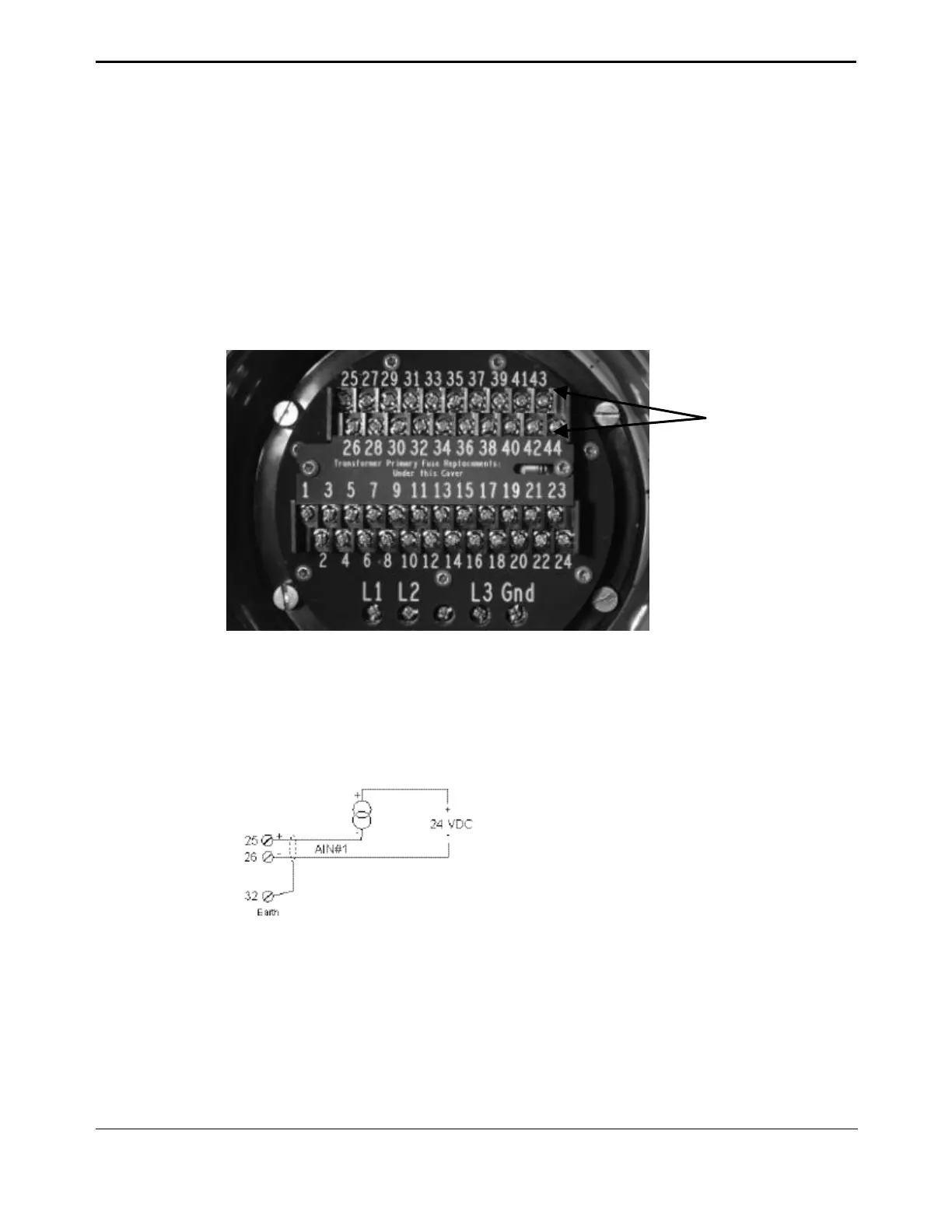
Figure 3-6 ACM Wiring Connections
3.6.2. Analog Controlled – Power Supply Connections
The power sources for analog controlled inputs/outputs are either internal or external.
Connect the power supplies as shown in Figure 3-7 through Figure 3-14.
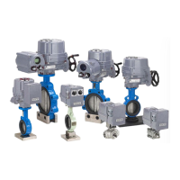
Figure 3-7 Futronic – Analog Input with External Power Supply
Figure 3-8 Futronic – Analog Input with Internal Power Supply
ACM Wiring
Terminals 25-44