3. Installation
TEC 2000 Installation & Operation Manual E2K-405-0902
3-14
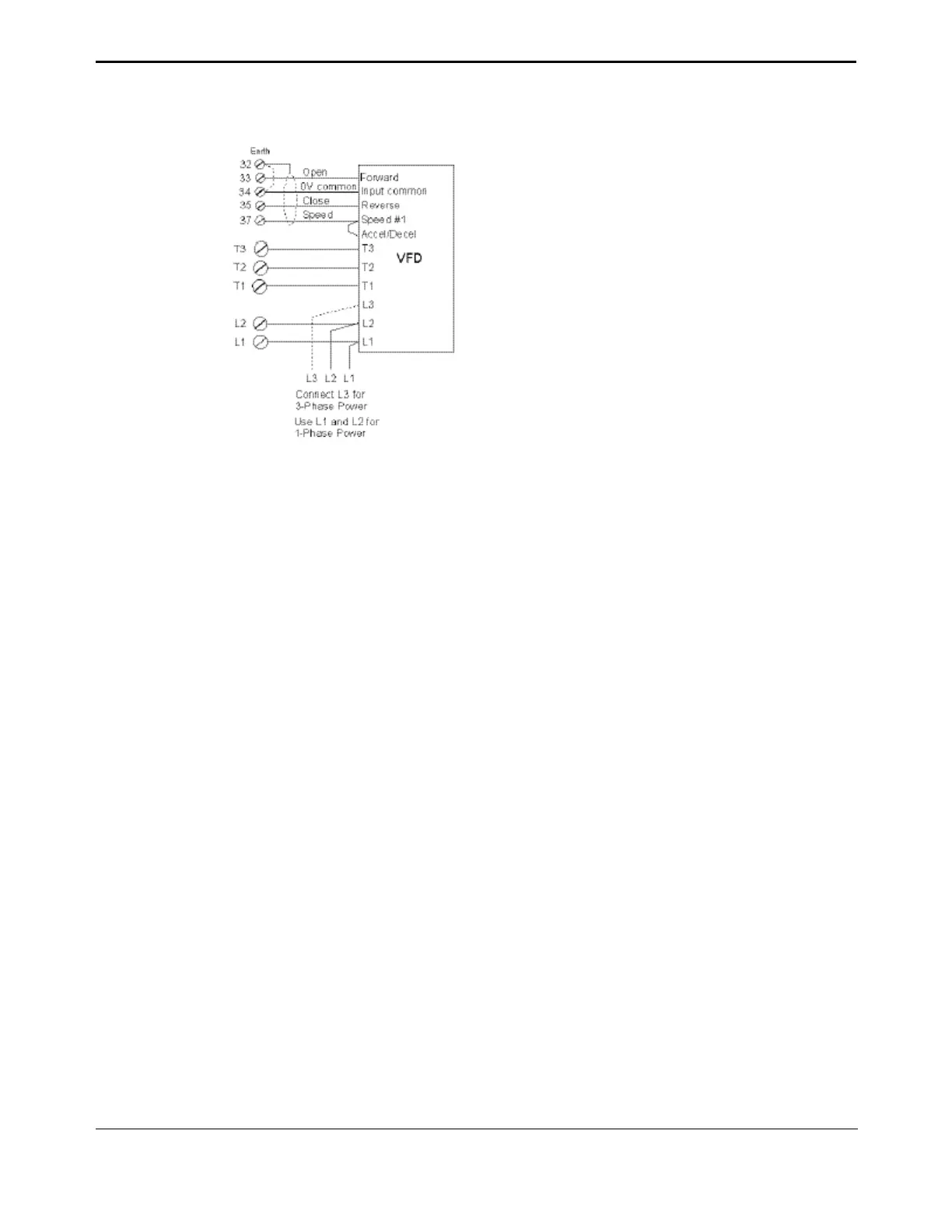
Figure 3-16 External VFD Control Wiring
3.6.4. Network Controlled
For the actuator to be network controlled, a Controlinc ACM and a Communication Adapter
Module (CAM) must be installed. Each CAM is required for a specific protocol and network
topology, and enables the network capability. To install the Controlinc ACM see Section
3.6.1, Wiring the ACM.
NOTE: Factory personnel must install the ACM and CAM. These modules (CAMs) may be
installed in the field only by factory-trained technicians using a special passcode to enter the
“FACTORY SETUP” mode.
Connect the actuators as shown in Table 3-5 for RS-485 redundant bus or E>Net networks.
If another protocol is selected then refer to the wiring diagram supplied with the actuator for
connections.
NOTE: If E>Net network topology is specified, insert a jumper between Terminals 40 and 42
to connect the network cable shield throughout the network and connect a single point earth
ground elsewhere.
See Section 3.3, Electrical Connections for general electrical connection requirements.