18
boiler to evacuate the condensates.
When type B installation is used, the
room in which the boiler is installed
must be ventilated using a suitable
air inlet which complies with current
legislation.
,Q URRPV ZKHUH FRUURVLYH YDSRXUV
may be present (for example, laundry
rooms, hair studios, rooms where
galvanic processes take place, etc.) it
is important that type C installation is
used, with air for combustion drawn
IURPRXWVLGH,QWKLVZD\WKHERLOHULV
protected from the effects of corrosion.
When implementing coaxial
suction/exhaust systems the use of
authentic accessories is obligatory.
7KH ÀXH JDV H[KDXVW GXFWLQJ PXVW
not be in contact with or placed near
ÀDPPDEOH PDWHULDOV DQG PXVW QRW
cross building structures or walls
PDGHXVLQJÀDPPDEOHPDWHULDO
This Boiler has an integrated high
OLPLW WKHUPRVWDW IXQFWLRQ IRU WKH ÀXH
JDVHV :KHQ WKH ÀXH JDV WHPSH-
rature exceeds 90ºC, the burner is
switched off. With this function, an
additional (external) safety device is
not necessary.
When replacing an old boiler, the
YHQWLODWLRQ DQG ÀXH JDV H[KDXVW
system must always be replaced.
7KH ÀXH JDV H[KDXVW GXFWLQJ
joint should be created using a
male/female coupling and a seal.
Couplings should always be arranged
so that they go against the direction
RIWKHFRQGHQVDWHÀRZ
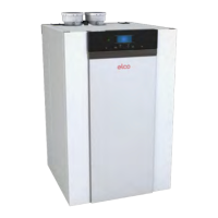
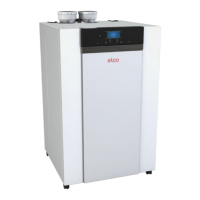
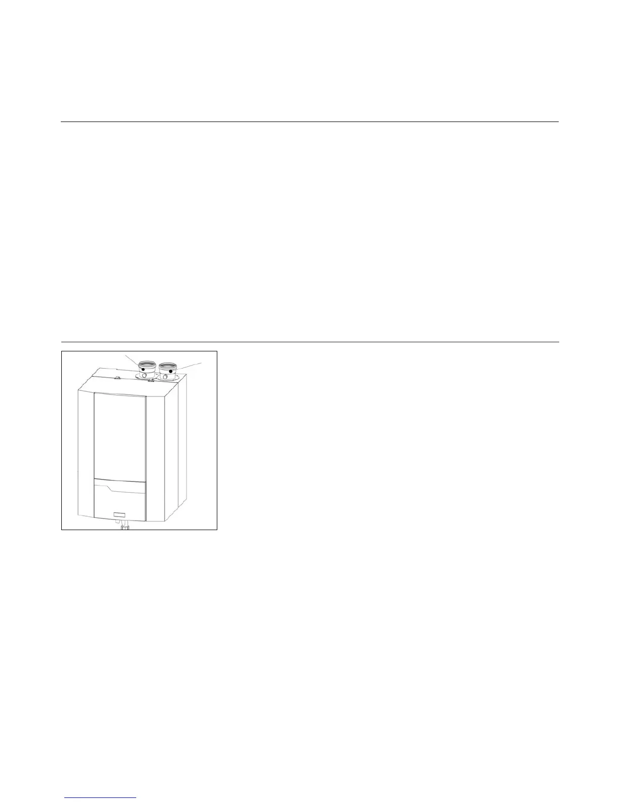
Flue gas connection (7)
The boiler is designed to operate in B
mode (by drawing air from the room)
and in C mode (by drawing air from
outside).
When installing an exhaust system
be careful when handling the seals,
LQRUGHUWRDYRLGÀXHJDVOHDNLQJLQWR
the air circuit.
&RQQHFW WKH ÀXH JDV V\VWHP WR WKH
ÀXHJDVFRQQHFWLRQRIWKHERLOHU
XVH ÀXHJDV V\VWHPV ZLWK VHDPOHVV
connections only.
,W¶VQRWQHFHVVDU\WRPDNHDVHSDUD-
WHFRQGHQVDWH GUDLQ IRU WKHÀXHJDV
system, as the condensate will be
drained via the syphon of the boiler.
The horizontal kit must be tilted with
a downward slope of 3° towards the
Air intake connection
The air intake can be connected in
case of room sealed installation.
The diameter should be calculated
according to the national regulations,
WRJHWKHU ZLWK WKH ÀXH JDV V\VWHP
The total resistance of both systems
should never overcome the maxi-
mum permissible resistance of the
fan inside the boiler (see also
FKDSWHU7HFKQLFDOGDWD
Installation
Air/Flue gas system
Requirements and regulations
Regulations for the construction of
ÀXH JDV V\VWHPV DUH YHU\ GLIIHUHQW
IRUHDFKFRXQWU\ ,W VKRXOG EHHQVX-
red that all national regulations with
UHJDUG WR ÀXH JDV V\VWHPV DUH UH-
spected.
Pay attention to the following recom-
mendations when dimensioning a
ÀXHJDVV\VWHP
2QO\DSSURYHGÀXHJDVPDWHULDOPD\
EH XVHG 7KH ÀXH JDV V\VWHP PXVW
be properly calculated to ensure a
safe functioning of the system.
Flue gas system components should
be removable for maintenance pur-
SRVHV+RUL]RQWDOÀXHJDVZD\VPXVW
be mounted under an angle of 3º mi-
nimum.
7KLV%RLOHULVFHUWL¿HGIRUWKHÀXH
gas systems B23(P), C13, C33, C43,
&&DQG&
Materials
Exclusively materials, which are heat
UHVLVWDQWDQGUHVLVWDQWWRÀXHJDVHV
and aggressive condensate, and CE
approved may be used.
,QSDUWLFXODUIRUÀXHJDVV\VWHPVHH
tab. on next page.
7