Installation 2-5
IQ 2000/5000 Installation Manual
Installing the Firmware EPROMs
1. Check that power to the PDM is OFF.
a. IQ-2000: Measure voltage between PDM terminals marked L1 and L2/N (and L3 on
PDM-75) to ensure incoming power is OFF. Also measure voltage between termi-
nals marked L1 AUX and L2/N AUX if used, to ensure power is OFF. The green DC
BUS LED and the bicolor STATUS LED should be OFF.
b. IQ-5000: Measure voltages at Positive and Negative bus terminals to ensure incom-
ing power is OFF. If a PSM-AUX is used, measure the voltage at L1 and L2 of the
PSM-AUX to ensure that incoming power is OFF
2. Remove PDM cover.
3. Install the four EPROMs on the PDM logic board in sockets U57, U66, U67 and U87. The
end of the EPROM with the notch must be toward the front of the PDM.
4. Install the PDM cover.
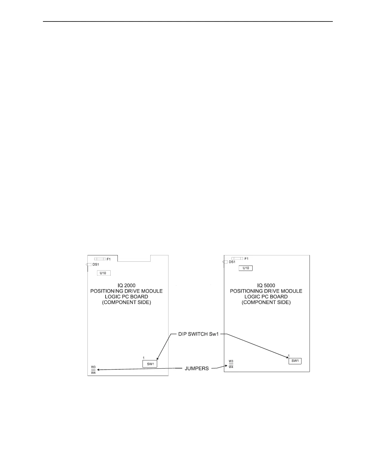
Jumper and DIP Switches
Jumpers W3 and W4 may be removed if an external 24 VDC power supply is used. Removing
these jumpers will disconnect the internal supply. The jumpers do not need to be removed if
only the 24 V common (P1 pin 1) is connected to machine common, but must be removed if an
external +24 VDC supply is connected to P2 pin 12.
Dip switch SW1 sets the address when multiple IQs are connected in multi-drop serial commu-
nications mode, and sets the mode of operation for the Operator Terminal serial port (port 1).
Refer to “Networking the IQ Operator Terminal” on page 3-20 for more information.
Refer to Figure 2.3 for the locations of jumpers W3, W4, and dip switch SW1 on the PDM logic
board.
FIGURE 2.3 Location of Jumper and DIP Switch