3-6 Wiring
P/N 0013-1027-005 Rev A
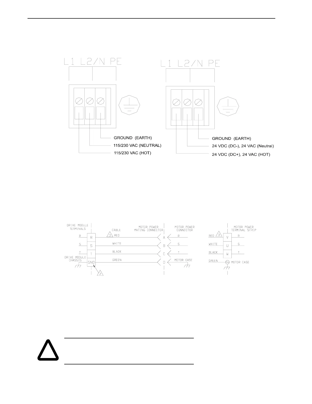
Operator Terminal
Figure 3.5 illustrates the power connections to the Operator Terminal 115/220/230/240 VAC
single phase (9101-2017) or 24 VDC/VAC (9101-2064). It must be properly grounded to prevent
radiating radio frequency noise.
Motor Power Connections
Phasing of the three-phase drive module outputs R, S, and T must conform to the motor R, S
and T leads for proper operation. Connect the earth ground to ensure a safe installation and
proper operation. Refer to Figure 3.6 for connector, pin and signal identification.
FIGURE 3.5 Operator Terminal Power Connections
FIGURE 3.6 Motor Power Connections
!
WARNING: High voltage may be present on terminals of the
IQ 2000/5000 Positioning Drive Module. Remove power and dis-
connect the power cable before making or removing any
connection.
NOTES:
1. Do not interchange any connection in this cable
2. Ground connections:
IQ-2000 – screw terminal
IQ-5000 – M6 stud
3. Wire colors shown reflect cables supplied by Electro-Craft
H-series,
S-series and
F-series motors
I-5300 and
I-5500 motors