Installation 2-27
IQ 2000/5000 Installation Manual
Low Voltage Directive
The drives must be mounted in an enclosure that provides a minimum of IP4X protection, such
that only skilled, authorized individuals may gain access to them.
The IQ 2000 has sinking (active low) I/O which is common in the US, but sourcing (active high)
I/Os are preferred in Europe. Rockwell Automation offers a DIN rail mounted card which
converts the I/O from sinking to sourcing. This card must be mounted in the same enclosure
as the drive.
Part numbers for the I/O conversion card and 3-foot and 10-foot interface cables are listed below:
◆ 24V Sourcing I/O Conversion Card
9103-0152
◆ 3 foot Conversion Cable
44-0141-003
◆ 10 foot Conversion Cable
44-0141-010
Some machines require that a contactor be inserted between the motor and drive for emergency
stop purposes. A hazard analysis of the machine will determine if this is needed. If used, the
contactor must not simply break the motor current, it must switch a 3-phase resistive load in
parallel with the motor windings. The three resistors provide dynamic braking and a category
zero stop. The resistors also prevent continuous arcing at the main contacts when breaking DC
currents, such as when the motor is at stall. Simply breaking the motor current can result in very
high voltages due to motor inductance which will cause prolonged arcing in the contactor. The
contactor could catch fire in extreme cases.
A contactor was simulated in most EMC tests by breaking the motor lead and taking it through
large rail mounted terminals. This simulates a closed contactor, which is acceptable as the con-
tactor would be closed for normal operation of the drive. The method of connection of the screen
and ground cables was as shown below. The shields should be unbraided, rather than soldering
a drain wire to the shield. Connection lengths should be minimized.
Note that the safety ground (GND) and shield connections are permanently connected. This is
essential for electrical safety. Note also that the safety ground is not connected to local ground
at the point where the contactor is inserted in the lines, but the shield is. This is done for EMC
reasons.
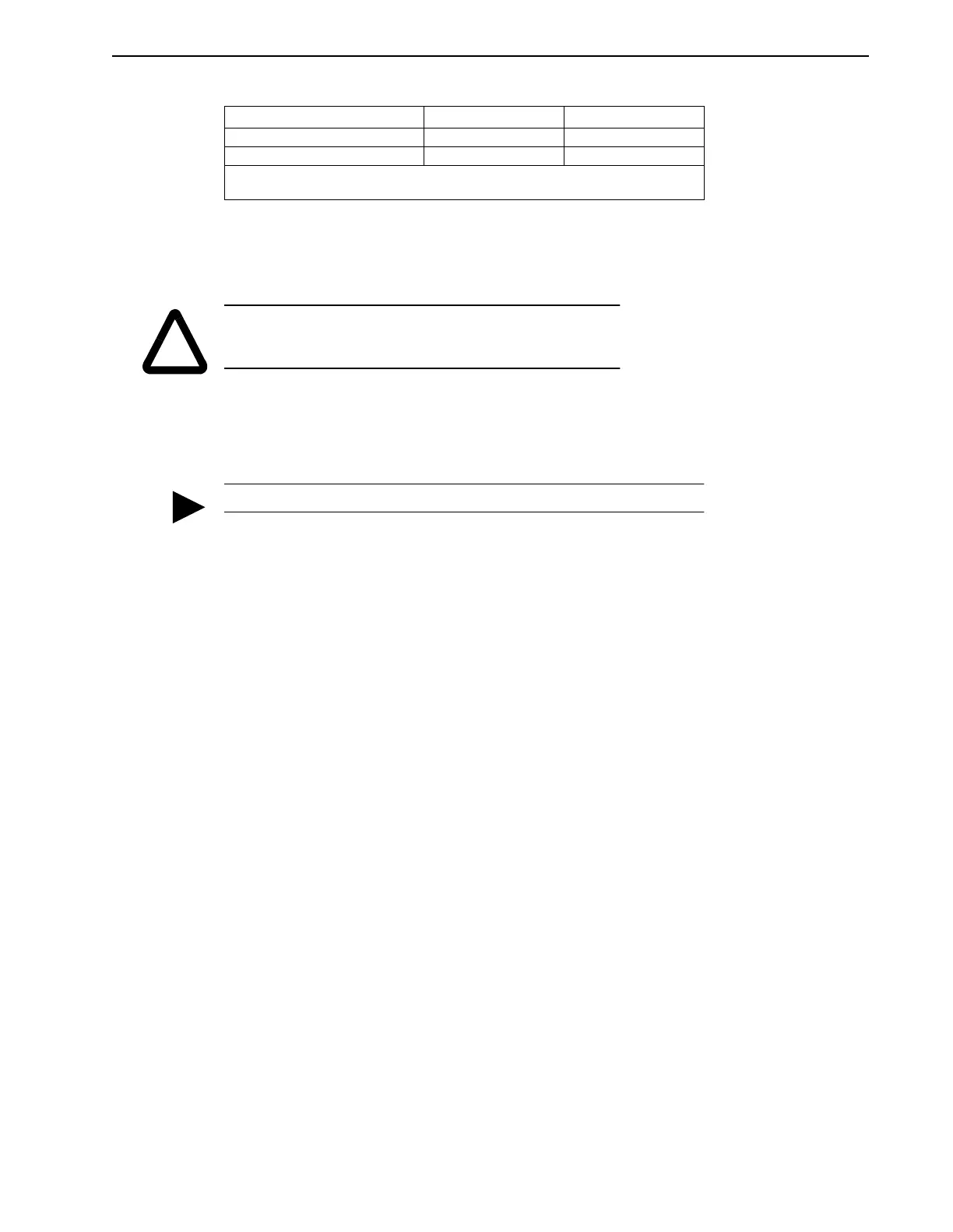
S-, H- & F-Series 6300 9101-1399-xxx
1
S-, H- & F-Series 8000 9101-1384-xxx
1
1. xxx is a 3 digit length call out, 010 = 3m (10 ft), 025 = 7.68 m (25 ft), 050 = 15 m (50 ft),
075 = 23 m (75 ft), 100 = 30 m (100 ft)
!
CAUTION: Motor connectors are for assembly and disassembly
only. These connections should never be made or broken while
the drive is energized.
A user supplied external 24VDC power supply is required for this option.
TABLE 2.6 Shielded Motor Power Cables (continued)
Motors Rockwell - USA Rockwell - Crewe