Wiring 3-7
IQ 2000/5000 Installation Manual
Cable sizes are indicated in the appropriate drawings:
◆ Figure 3.27 on page 3-27 for the PDM-10, PDM-20 and PDM-30 (IQ-2000)
◆ Figure 3.28 on page 3-28 for the PDM-75 (IQ-2000)
◆ Figure 3.29 on page 3-29 for the PDM-150B (IQ-2000)
◆ Figure 3.25 on page 3-25 for the IQ-5000.
Standard cables supplied by Electro-Craft are not intended for applications where frequent
flexing occurs. The motor connectors are intended to be connected or disconnected only when
the system power is off, and must not be used to disconnect live equipment.
Shield Termination of Power Cables
F-, H-, N- and S-Series Power Cables
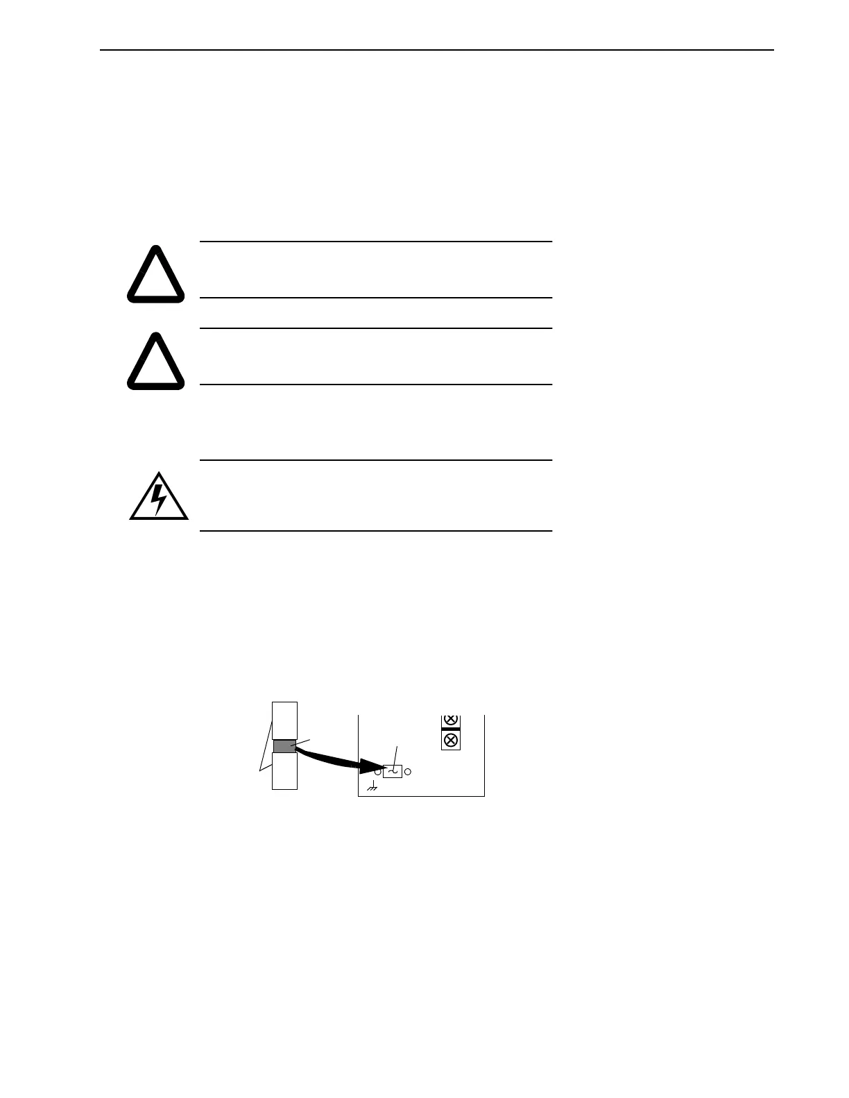
Electro-Craft motor power cables are shielded. The power cable is designed to be terminated at
the drive during installation. A small portion of the cable jacket is stripped, which exposes the
shield wires. The exposed area must be clamped at the left front of the drive chassis using the
clamp provided near the bottom. It is critical for EMC performance that the shield wires be
clamped against the area of the chassis which is not painted. This section of the chassis is labeled
with the chassis ground symbol.
Drawings which illustrate the power connections for specific F-Series, H-Series, N-Series,
S-Series, W-Series, and I-Series motors are supplied with the motors and are available in the
Electro-Craft catalog or via the Electro-Craft BBS.
!
WARNING: Motor power connectors are for assembly purposes
only. They should
not
be connected or disconnected while power
is applied to the drive.
!
CAUTION: Do
not
tin (solder) the exposed leads on cables. Sol-
der contracts over time and may loosen the connection.
DANGER: Shielded power cables must be grounded at a mini-
mum of one point for safety. Failure to ground a shielded power
cable will result in potentially lethal voltages on the shield and
anything connected to it.
Intro
FIGURE 3.7 Motor Power EMC Shield Connection
Masked area
Shield
Cable Jacket