3-4 Wiring
P/N 0013-1027-005 Rev A
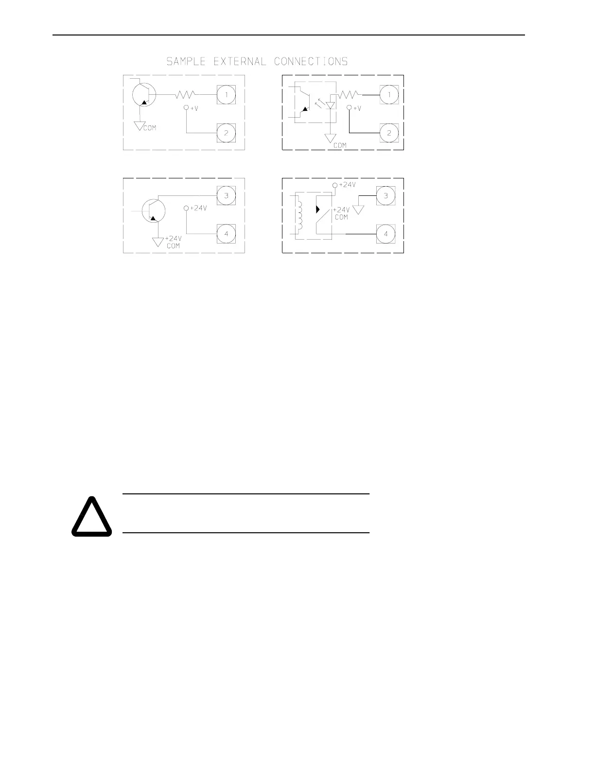
Status
The Status outputs are the contacts of a normally open relay, which closes to indicate that the
PSM is operating properly. An open relay signals that no AC power is applied to the PSM or
that a PSM fault has occurred. Refer to the above drawing for connection examples.
Enable
The PSM Enable input is an optically isolated input which controls the power output of the
power supply module. The PSM Enable input is turned on by sourcing current through the
opto-isolator. Refer to the above drawing for connection examples. The input is only functional
if jumper W1 is in the optional position, A (see figure below).
With the jumper in the enable input activated position (optional Position A), the PSM is enabled
if the enable input is ON. With the enable input OFF, the PSM DC bus is turned OFF and the
dissipative shunt is turned ON to quickly discharge the DC bus capacitors and dynamically
brake synchronous motors. This is to allow time for the PDMs to power-up and apply the enable
signal to the PSM if the PSM is to remain ON.
With the jumper in the enable input deactivated position (standard Position B), the enable input
has no effect on the PSM operation and the PSM activates itself when three phase voltage in the
proper voltage range is connected to the input.
Replacing the PSM Shunt Fuse (IQ-5000 only)
The DC Bus shunt fuse is located in the Power Supply Module. To check and/or replace this fuse:
1. Measure voltages at L1, L2, and L3 phase to phase to ensure incoming power is OFF.
Make sure that the green PSM READY LED is OFF. Remove the PSM cover.
FIGURE 3.2 PSM Interface – External Connection Examples
!
WARNING: If the PSM is disabled during a power up, the DC bus
voltage will be present for at least two (2) seconds before returning
to a zero (0) Volt condition.