3-22 Wiring
P/N 0013-1027-005 Rev A
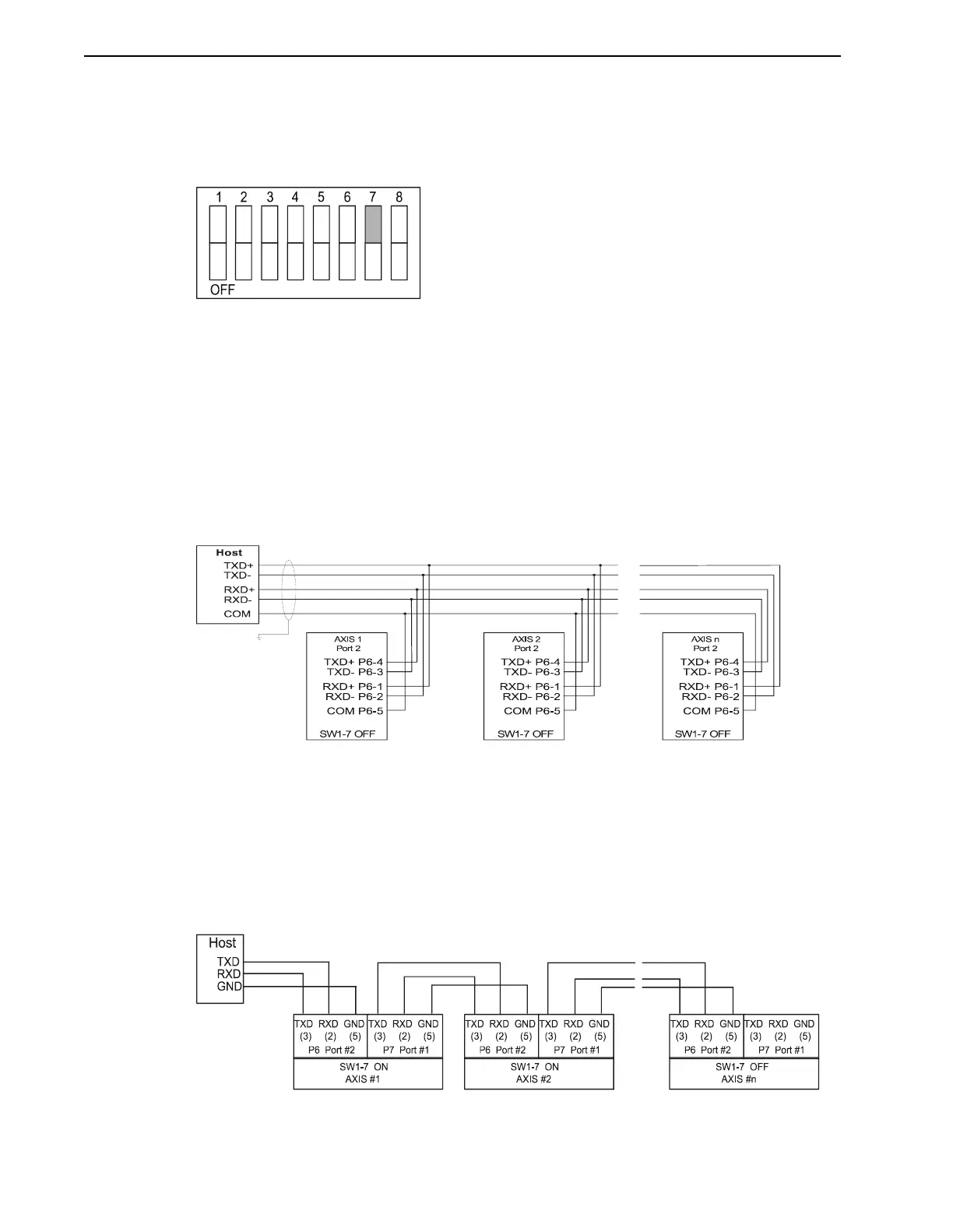
Figure 3.22 illustrates the setting of SW1-7 ON for the daisy-chain mode. Switch SW1-7 is used
to select the mode of operation of the serial port 1. If SW1-7 is OFF, serial port 1 functions as an
independent serial port. If SW1-7 is ON, serial port 1 and serial port 2 are linked together (daisy-
chained). Any data that is received on one serial port is automatically transmitted out the other
serial port.
Switch 8 on the DIP switch is not used. The PDM is shipped with all switches set to OFF, for
independent operation of the serial ports and the address set to 0. If there is only one PDM in
the system, all of the switches on DIP switch SW1 should be OFF.
RS-422 Multi-Drop
Figure 3.23 illustrates the connections needed for multiple PDMs, which can be linked with an
RS-422 multi-drop configuration. Remember to set a different address on DIP switch SW1 for
each PDM on the RS-422 network. The cable used for these connections should be 22 AWG
twisted pair with an overall shield grounded at one point.
RS-232C Daisy-Chain
The two serial ports can also operate as one port with the transmit and receive lines fed through
for multiple connections. Switch 7 on DIP switch SW1 selects the independent or daisy-chain
operation of the two serial ports. Remember to set a different address for each PDM in the chain.
The cable used for these connections should be 22 AWG twisted pair with an overall shield
grounded at one point.
FIGURE 3.22 Dip Switch SW1-7 Set ON For Daisy-Chain Mode Example
FIGURE 3.23 RS-422 Multi-Drop Connections
FIGURE 3.24 RS-232C Daisy-Chain Connections