Installation 2-13
IQ 2000/5000 Installation Manual
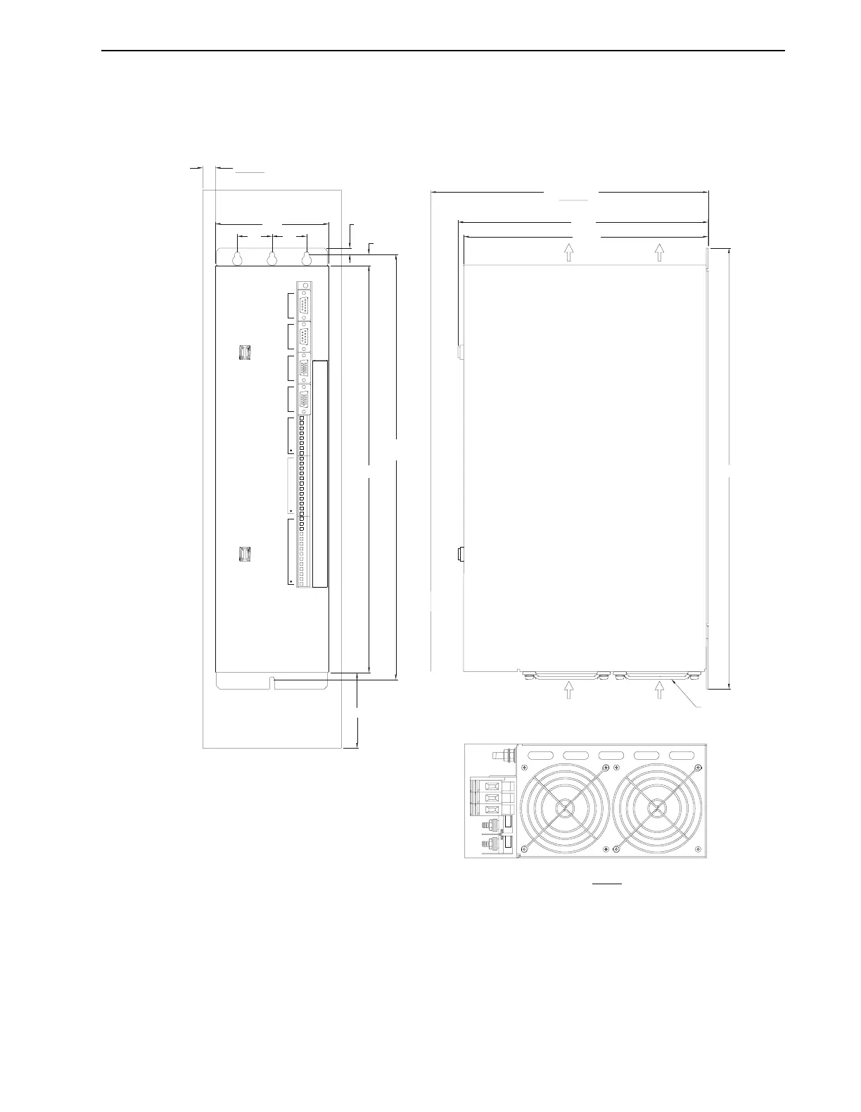
IQ-5000 Positioning Drive Module and Power Supply Module
The power supply module should be centrally located to minimize the distance between it and
the drive modules. The higher current rating drive modules should be located closest to the
power supply module. Figure 2.9 illustrates dimensions and mounting requirements.
FIGURE 2.9 IQ-5000 PDM & PSM Mounting
POS NEG
RST
GENERAL PURPOSE
INPUTS
GENERAL PURPOSE
INPUTS AND OUTPUTS
ANALOG
I/O AND STATUS INPUT 2
ENCODER ENCODER
INPUT 1 PORT 1
SERIAL
PORT 2
SERIAL
P7
P6
P5
P4
P3
P2
P1
DO NOT APPLY POWER WITH COVER REMOVED.
DO NOT REMOVE COVER WITH POWER APPLIED.
DANGEROUS VOLTAGES MAY EXIST UP TO 5
MINUTES AFTER REMOVING POWER.
WARNING:
VIEW "B"
"A"
AIR
SEE VIEW A
"B"= 0.50(13.0)MINIMUM FOR AIRFLOW BOTH SIDES OR BETWEEN ADJACENT UNITS.
2. "A"= 4.00(102.0)MINIMUM FOR AIRFLOW,ABOVE AND BELOW UNIT.
"C"=11.00(280) CLEARANCE FOR CABLES.
1. MUST CONFORM TO SPEC. 7058-9978.
NOTES:
4.50
[114.3]
1.38
[34.9]
1.38
[34.9]
0.25
[6.3]
0.45
[11.5]
16.15
[410.2]
16.88
[428.7]
VIEW "C"
9.93
9.70
17.50
[444.5]