3-24 Wiring
P/N 0013-1027-005 Rev A
Crimp connectors and a connector housing for expanded analog signals are included in the
expansion card kit. Use 0.34-0.08 mm
2
(22-28 AWG) stranded wire. Noise sensitive applications
may require twisted shielded wire pairs, in which case the shield is grounded at one end only.
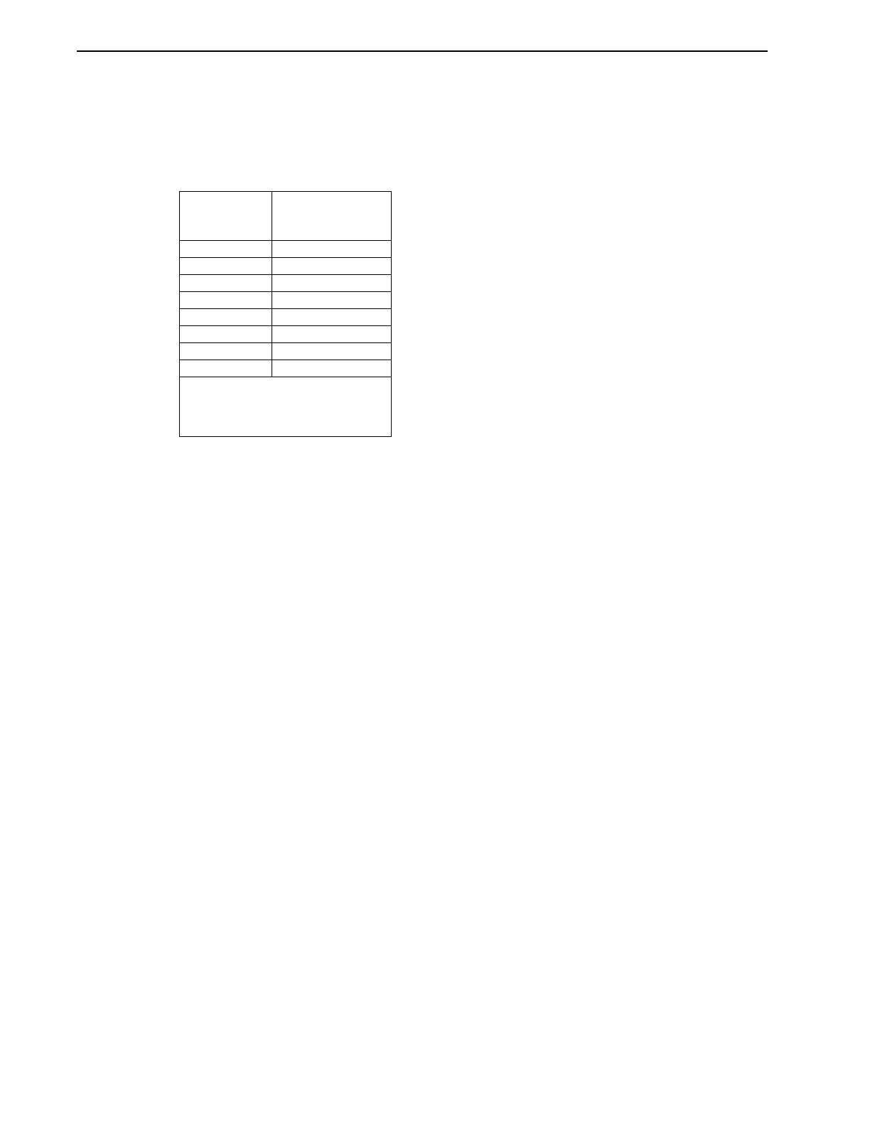
Table 3.16 defines the relationship between P3 user-crimped leads and the housing supplied
with the kit.
The Monitor menu provides expanded I/O status. Refer to the IQ Master Instruction Manual for
additional information about expanded I/O display and status.
TABLE 3.16 P3 Pins on Expansion Card
IQ Analog
Input Number
Expansion Memory
and I/O Card
Connector and Pin
ADC2- P3-1
ADC2+ P3-2
ADC3- P3-3
ADC3+ P3-4
ADC4- P3-5
ADC4+ P3-6
ADC5- P3-7
ADC5+ P3-8
NOTE:
Pins P3-6 and P3-7 may be used to
supply +5 VDC to an I/O expansion
board.