Wiring 3-15
IQ 2000/5000 Installation Manual
Encoder 1
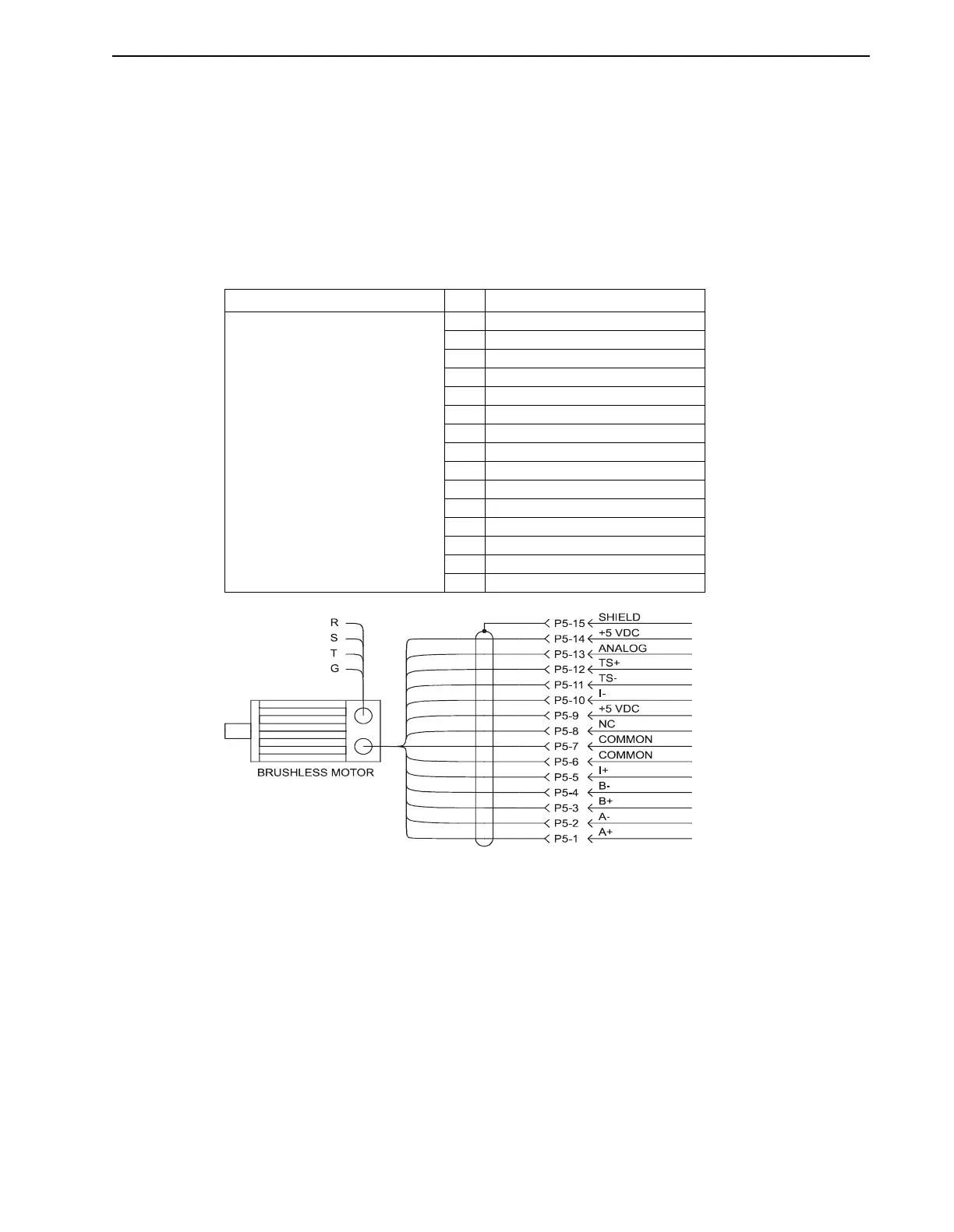
Figure 3.13 illustrates the connections of Encoder 1, which must connect to the encoder mounted
to the motor. This is the only motor mounted feedback necessary for control of the motor velocity.
This encoder is also normally used for position feedback. The Encoder 1 interface also includes
connections for the normally closed thermostat in the motor windings, and for an analog start-
up signal required for proper operation.
Refer to Figure 3.33 on page 3-32 and Figure 3.35 on page 3-33 for connections to H-, F-, or S-
Series motors.
TABLE 3.9 Encoder 1 and Signal Name
Encoder 2
Figure 3.14 illustrates the connections of Encoder 2, which provides an optional second encoder.
It can be used as position feedback directly from the load, or as a master input for relative
positioning, master-follower systems, or for electronic gearing.
As an alternative, the Encoder 2 port may also be used to output encoder 1 signals when only
the motor mounted encoder is used. The function of the Encoder 2 port is selected as input or
output in the Parameter menu, Feedback Configuration dialog box. Refer to the IQ Master
Instruction Manual for detailed information.
Connector Pin Signal Name
P5
Encoder input 1
1A+
2A-
3B+
4B-
5 I+ (Index)
6common
7common
8 no connection
9 +5 VDC
10 I- (Index)
11 TS- (thermostat)
12 TS+ (thermostat)
13 Analog (absolute position)
14 +5 VDC
15 Shield
FIGURE 3.13 Encoder 1 Connections