2-8 Installation
P/N 0013-1027-005 Rev A
Mounting
Before mounting the PDM, any installation of option cards, Personality Modules, and system
firmware should be completed. Other operations such as removing jumpers on the logic board
should also be performed before mounting the system.
Environment
The PDM and power supply modules are designed for simple installation on a flat surface such
as the back wall or plate of an enclosure. They must be enclosed in a grounded metal enclosure
offering protection as defined in standard EN 60529 (IEC 529) to at least IP54 such that they are
not accessible to an operator or unskilled person. A NEMA 12 enclosure exceeds these require-
ments providing protection to IP65. The environment in the enclosure must be clean and free
of oil mist, coolant mist, conductive particles, water and corrosive chemicals. The enclosure
must also be properly sized (and ventilated if required) to ensure that the maximum ambient
temperature of the PDM is not exceeded.
Ventilation
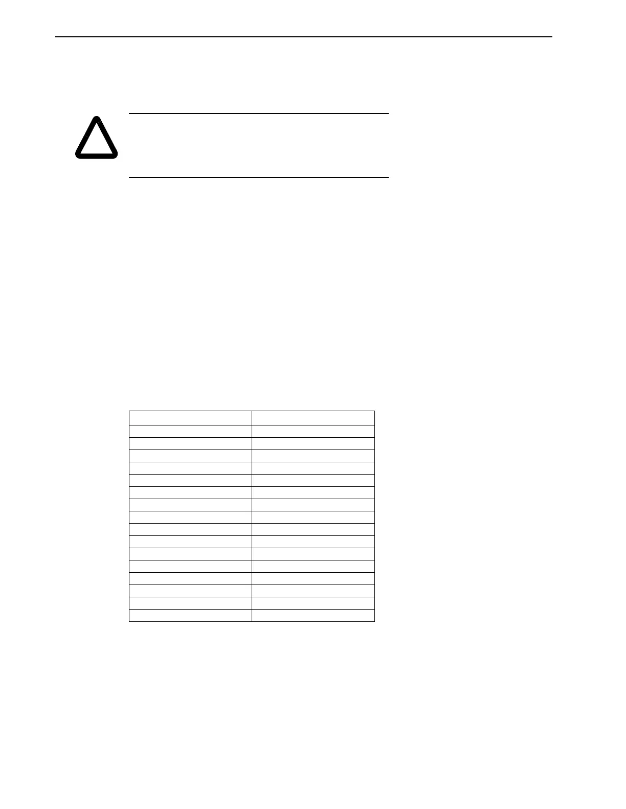
The maximum power losses are shown below to help in sizing an enclosure and any required
ventilation. Typical heat losses can run approximately one-half maximum power losses.
As an additional aid in sizing an enclosure, with no active method of heat dissipation, the
following approximate equation is used:
T = 4.08 (Q/A) + 1.1,
Where T is temperature difference between inside air and outside ambient (°F), Q is heat gen-
erated in enclosure (Watts), and A is enclosure surface area (ft²).
The exterior surface of all six sides of an enclosure is calculated as
A = (2dw + 2dh + 2wh)/144
Where d (depth), w (width), and h (height) are in inches.
!
CAUTION: Complete all drilling, cutting, welding, etc., before
mounting the equipment. During installation, protect equipment
from metal chips, weld splatters and other debris. Failure to
observe this precaution could result in damage to or destruction
of the equipment.
TABLE 2.2 Maximum Power Losses for IQ-Series Related Products
Model Maximum Loss (Watts)
PDM-10 50 + dissipative shunt
PDM-20 100 + dissipative shunt
PDM-25 120
PDM-30 150 + dissipative shunt
PDM-50 180
PDM-75 300 + dissipative shunt
PDM-100 275
PDM-150 300
PDM-150B 500 + dissipative shunt
PSM-50 110 + dissipative shunt
PSM-125 240 + dissipative shunt
Operator Terminal 25
3.0 kVA Transformer 350
TF-03 (3 kW transformer) 350
TF-06 (6 kW transformer) 600
TF-18 (18 kW transformer) 1200